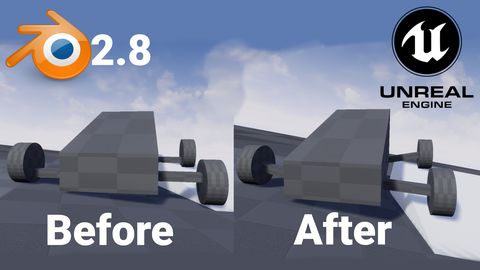
How to rig vehicle in Blender 2.8 for UE4
by Arthur Ontuzhan
Posted 7 years, 3 months ago Last edit 2 years, 3 months ago
Categories: Tutorials Blender Unreal Engine Tags: Vehicle Blender 2.8 UE4
Table of contents
Introduction
First time when I tried to rig a simple vehicle using Blender for UE4, it took several hours to get it working. And after several months or even years, I needed to rig another vehicle in Blender for UE4. I thought it will not take much time, at least not so much as before. But I was wrong, it took several hours again. So I made a tutorial on how to rig simple vehicle using Blender which will work in UE4.
In this tutorial I will show how to rig simple vehicle in blender 2.8 and how to get it working in UE4.
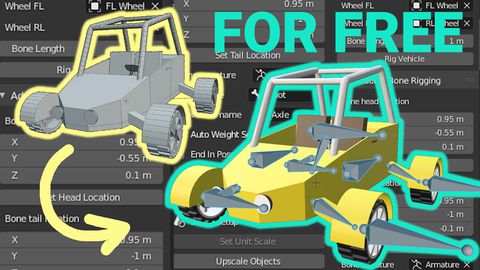
I made a free addon for Blender which will speed up vehicle rigging process, you can get it here.
Prerequisites
- Blender 2.8 or newer installed. (As I am creating this tutorial, I am using Blender 2.8 beta version, but it should not differ much in a stable release or newer versions.)
- Unreal Engine 4.21.2 installed. Any newer should also work, maybe some older versions also will work.
- Basic knowledge of how to use Blender and UE4.
Creation of a vehicle in Blender
Project setup
At the start, we need to have an empty Blender project. To get that, we have to open a new project, and then select everything and delete it.
- I prefer to do that by once pressing A key, then pressing X and then accepting deletion by hitting Enter or by mouse click.
- Or just do that your way.
After we have a clean empty project, we must change the scene Unit Scale to 0.01.
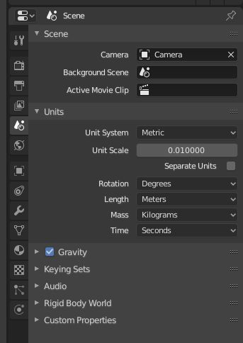
We can find Unit Scale in the bottom right side of the Blender window. There we should select Scene tab, expand Units section and we will see Unit Scale value, which by default is 1. Also, make sure that the Unit System is set to Metric because UE4 uses metric system.
We changed this value, because UE4 one unit is equal to 1 cm, but in Blender default unit value is 1 meter, that's why we scaled it down to 1 cm. If you have exported models from Blender to UE4 before, you might think you didn't do this and all worked as expected to you, then probably you didn't used armatures in your models.
After Unit Scale change, there will occur a problem in a 3D viewport, that we cannot see objects from further distances. This happens because with changing Unit Scale also 3D view end clipping distance changes.
Clipping distance determines how far and near we can see objects from our viewport camera in our scene. That's why we need to increase it.
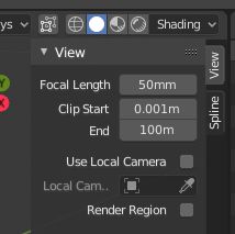
To increase 3D view Clip End distance, we need to press N key, which will open the properties menu on the top right corner of the 3D viewport.
There under the View section, we will see the End value, which will be set to 10m. I usually set it to 100m, because I am too lazy to add more zeros. Most of the time 100m is enough for me to move a camera around. If this distance is not enough for you, you can always increase it, by default it's set to 1000m.
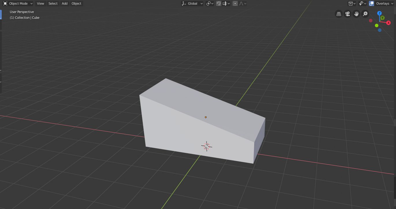
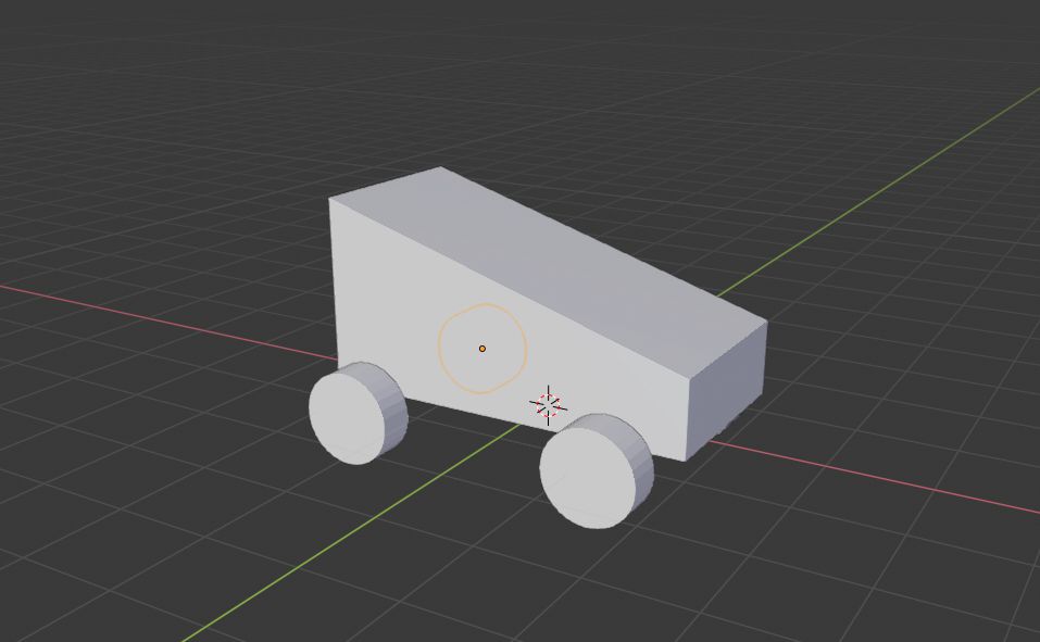
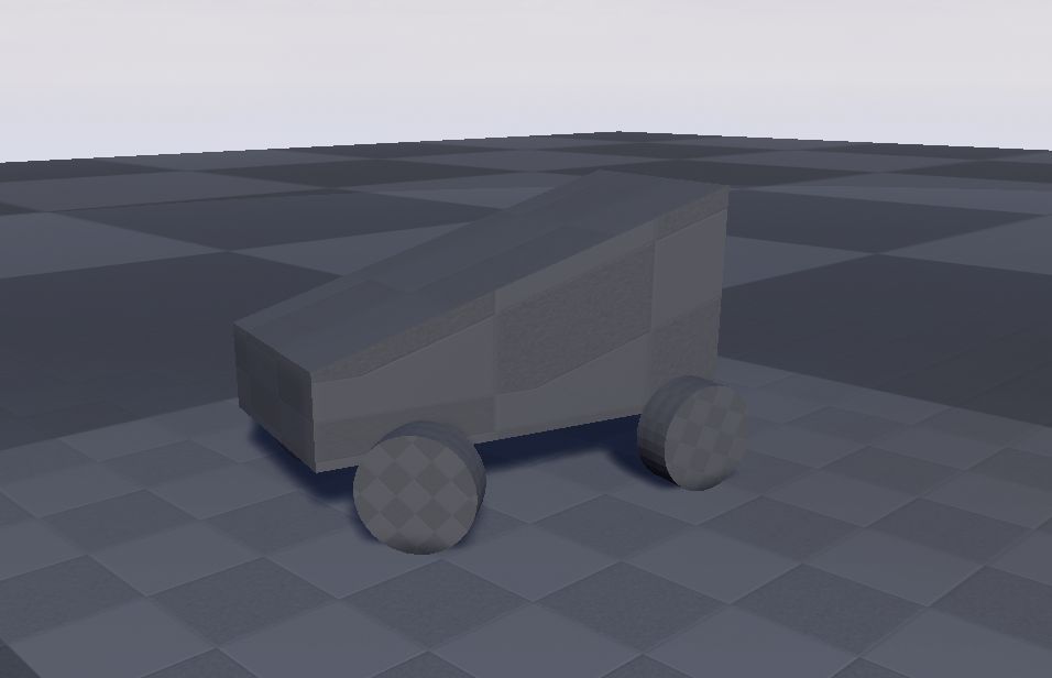
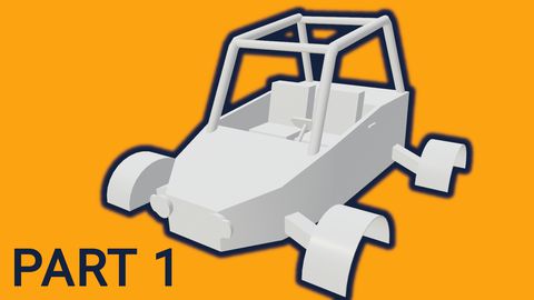
We can see that I made a simple vehicle base model. When you will model a vehicle, make sure, that your vehicle's front is faced to the positive X-axis. To see which axis is which look at 3D viewport's left upper corner. As we can see my vehicle's front is narrower than the back and it's facing to the positive X-axis.
If you want to make exactly the same model as I made you can follow these steps:
- Create cube - press Shift + A and then in Mesh sub-menu select Cube
- Move cube higher - press G then Z and type 1.2, press Enter
- Scale cube on X-axis - press S then X and type 2, press Enter
- Enter Edit mode and choose Edge select - press Tab and then 2
- Lower upper edge at positive X-axis side - select edge with a left mouse click, press G then Z and type -1.2, press Enter
- Exit edit mode - press Tab
Now we can add wheels to our vehicle.
We can see that my wheels are just simple cylinders.
If you want to get wheels exactly like mine, you can follow these steps:
- Create cylinder - press Shift + A and then in Mesh sub-menu select Cylinder
- Scale cylinder's width - press S then Shift+Z and type 0.5, press Enter
- Scale cylinder's height - press S then Z and type 0.2, press Enter
- Rotate a wheel to the standing position - press R then X and type 90, press Enter
- Move wheel to front left position - press G then X and type 1.2, press Enter then G then Y and type 1.2, Enter
- Make right front wheel - press Shift+D then Y and type -2.4, press Enter
- Make both rear wheels - select both front wheels by holding Shift and clicking on them with left mouse click then press Shift+D then X and type -2.8, press Enter
Now it would be good practice if we named each part of the vehicle, but if you are lazy, you can just leave them as they are.
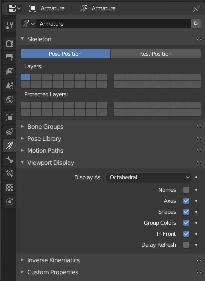
Properties which we need to change we can find in the bottom right side of the Blender window. There we should select Object Data tab, expand Viewport Display section. There we should see check boxes with names Axes and In Front, by default they are unchecked, make them Checked.
- By checking Axes armature bones will show their axes, which will help us to place bones in the right orientation.
- By checking In Front armature bones will be drawn in front of other objects, this will help us with bone placement in objects. In previous blender versions this property was named X-Ray.
Right now you may be confused because I explained that In Front setting will draw bones in front of all other objects, but you see a none bone in the viewport. We can't see it because it's too small, that's because we changed the Blender unit size to 1 cm so bone was created one unit big.
To see the bone, we need to scale it up. To scale it up, press S type 100 and then press Enter.

Now we can see bone through the vehicle base and see its axis. If we look closer, we can see that the bone axis is not aligned with the global axis. To get our rigged vehicle correctly working in UE4, we need to align all bone axis to the global axis. To do that we will just rotate our bone so axis would align.
To rotate bone to correct its orientation press R then X type -90 and press Enter. Also, because the bone is below the vehicle body, we will lift it up so it would be inside the vehicle body. To lift up bone, press G then Z and type 0.5 and press Enter.
Now we have the main bone which is correctly oriented. Now we need to extrude 4 more bones from this bone with correct axis orientation, one for each wheel. To do that we will follow these steps:
- Enter edit mode - press Tab
- Make sure that the whole bone or its outer part is selected, then press E then press Y and type 1 and press Enter
- Using a left mouse click select newly created bone
- Press Alt+P and select Disconnect Bone
- Move the bone to the side so there would be a place for other bones - press G then X and type -0.75, press Enter
- Create another bone for wheels - press Shift+D then press X and type 0.5, press Enter
- Repeat previous step 2 more time to get in total 5 bones, one in the vehicle base and 4 for the wheels.
- Exit edit mode - press Tab

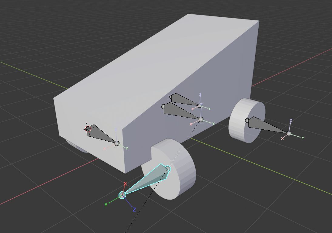
Since we have all bones for the wheels, we can now position each of them in their wheel positions. To do that we will follow these steps:
- With the right mouse click select one wheel and press Shift+S, then press 2 or click Cursor to Selected
- Select armature and then go in edit mode by pressing Tab, then select one of the wheel bones
- Press Shift+S and then press 8 or click Selection to Cursor
- Exit edit mode by pressing Tab and then repeat all these steps until each wheel has its own bone
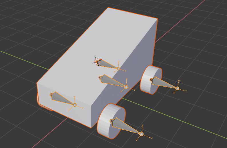
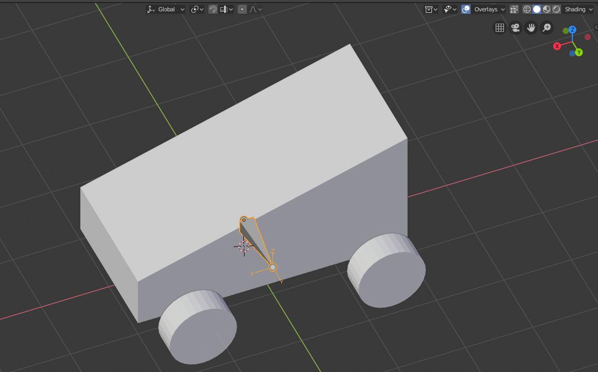
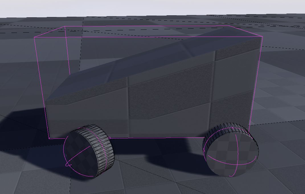
When you are done with bone placement, you should get a similar result like in the image above. Before we can parent mesh to armature and weight it, but before that we need apply scaling and rotation to meshes and armature.
To apply scaling and rotation to all objects we select all objects by pressing A and then we press Ctrl+A and select Rotation & Scale.
Also it's good practice to name each armature bone. Naming will help us with the mesh weighting and setting up it in UE4.
You can name bones by selecting armature with a left click, and then entering edit mode by pressing Tab. Then you can select each individual bone by left clicking them and then you can change their name in the bottom right side of the Blender window in Bone tab top part.
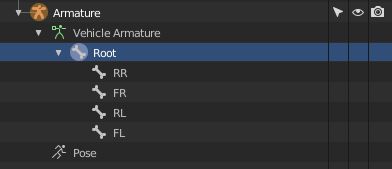
I renamed each bone by its wheel's position. Also, I renamed the first bone to Root.
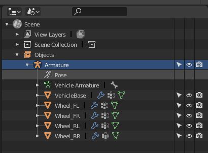
Now we can parent mesh to armature and weight it. To do that, we need to be in object mode and have selected all meshes and armature. Make sure, that armature is active when all objects are selected. Active object has lighter highlight around it. You can see how correct selection looks 2 images above. You can select and change active object by Shift left clicking object.
After selection is made, we can parent meshes to armature by pressing Ctrl+P and then selecting With Empty Groups.
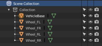
If we look at Blender window right top side, we will see outliner there, and if we change its Display Mode from View Layer to Scenes, we should see in a tree hierarchy that armature now is parent to all meshes.
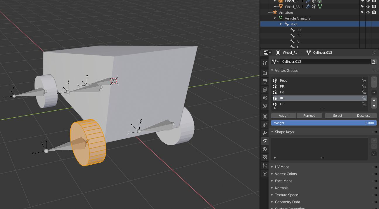
If we would go in pose mode now and try to move any of the bones, we would see, that they aren't moving any mesh with them. That's why we need to weight meshes. To that, we will do the following steps:
- In the object mode with the left mouse click we will select one of the meshes
- Enter in edit mode by pressing Tab and make sure that all mesh is selected, we can select all mesh by pressing A
- In the bottom right side of the Blender window we open the Object Data tab and expand the Vertex Groups section
- We select the group which corresponds to our selected mesh and click Assign
- Exit edit mode by pressing Tab and repeat these steps for all meshes (For vehicle body set Root group)
Now our vehicle should be ready for exporting, but before we do that, let's check if we assigned all vertex groups correctly. We will do that by looking if in pose mode each bone and its mesh counterpart reacts as they should.
- In object mode select armature
- Enter pose mode by pressing Ctrl+Tab
- Select one bone with the left mouse click
- Move bone around by pressing G or rotate it around by pressing R, stop movement with right mouse click
- If with bone is moving its corresponding mesh, then the mesh is assigned to the correct vertex group (Root bone should move all mesh and bones)
- If with bone is not moving corresponding mesh or also moving other mesh, then recheck mesh vertex groups
- Repeat these steps for all bones
Exporting vehicle
Finally, we can export our vehicle and import that in UE4. To export vehicle we will do following steps:
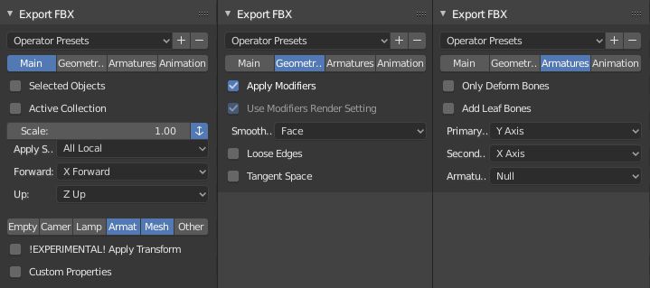
- Click on File->Export->FBX (.fbx)
- With Shift click make sure that in a Main setting tab only Armature and Mesh are selected as exportable objects
- In the same Main tab change Forward: to X Forward and Up: to Z Up
- In a Geometries tab set Smoothing to Face
- In an Armatures tab uncheck Add Leaf Bones
- Choose place and name for your file and press Export FBX
We are done with file exporting. But don't close Blender yet. We need to know our vehicle wheel sizes, so we could set them up correctly in UE4.
To do that we need in object mode select one wheel and then at the right side of the viewport we should see its Dimensions in properties menu under Transform section, if you don't see properties menu, you can toggle it by pressing N.
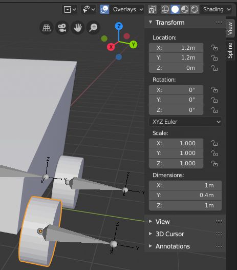
If you made vehicle exactly the same as I did, you should see that X and Z dimensions are 1 m and Y dimensions is 0.4 m. For UE4 we need to know wheel radius and half of it's width, in this situation wheel radius will be 0.5 m and half width will be 0.2 m.
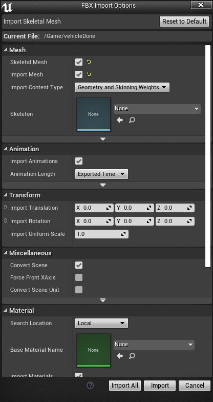
Setting up the vehicle in UE4
We will set up our vehicle in an empty UE4 project. So we will start by creating a Blank Blueprint project.

We can see that our all vehicle physic bodies are made of capsules. Capsule collision may be acceptable for vehicle body physics collision, but capsules for wheels not so much. Especially when capsules are in a standing position. We will regenerate all physics assets. So we need to delete all existing physics bodies.
- Press Ctrl+A to select all physics bodies
- Press Delete to delete all selected physics bodies
Now we need to regenerate new physics bodies for our vehicle.
- Select Root bone in Skeleton Tree tab
- In a Tools tab for Primitive Type select Box and make sure that Auto Orient to Bone is disabled
- Click on Add Bodies button, we should now see a new box physics collision generated
- Select all Wheel bones in Skeleton Tree tab
- In the Tools tab for Primitive Type select Sphere
- Click on Add Bodies button, we should now see new sphere physics collisions generated for our wheels
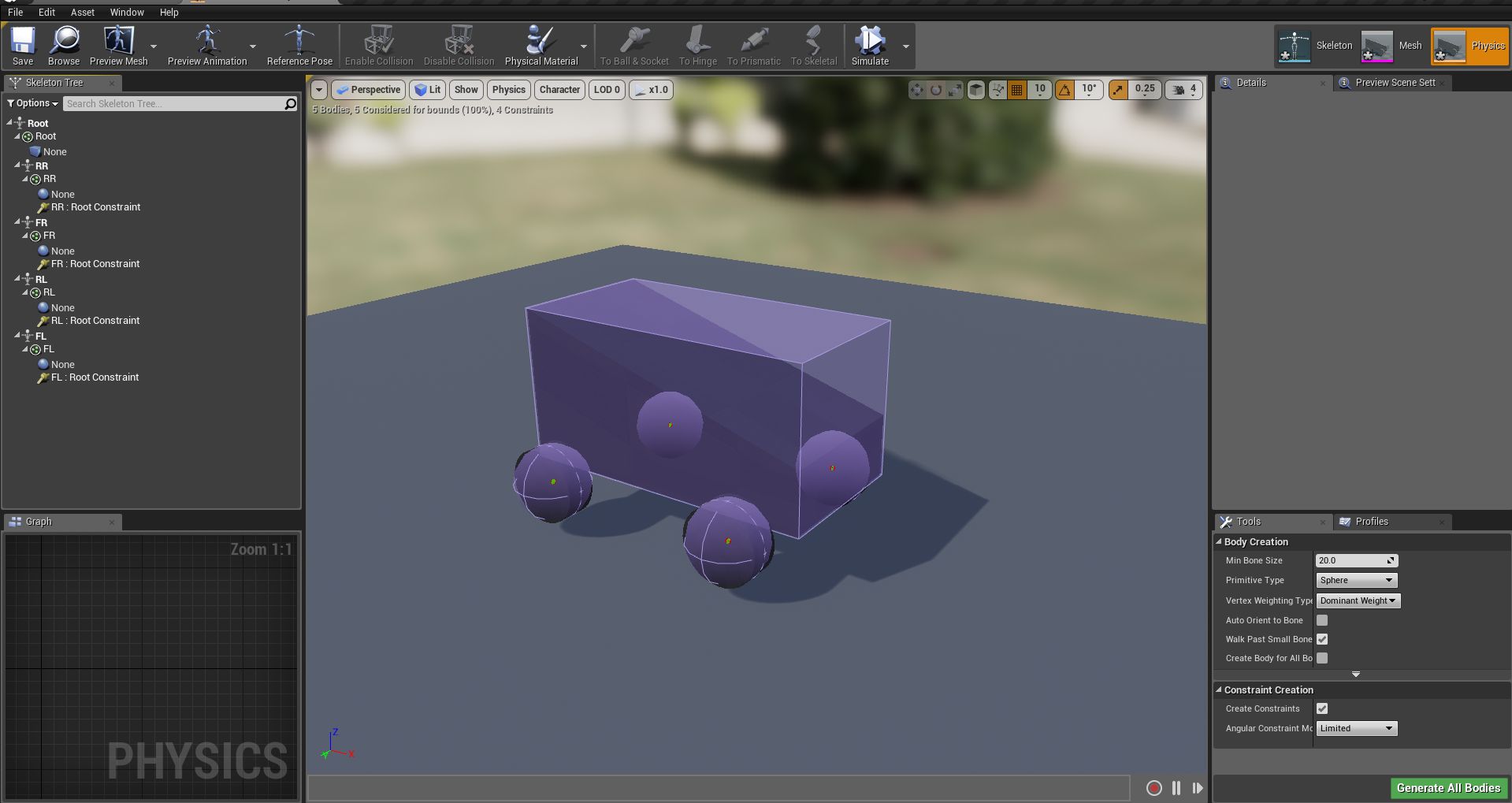
We need to have at least physics body for the root bone, otherwise our vehicle will not move. Our vehicle will be ridable even without wheel physics bodies, but it's recommended to have those, so our vehicle would have better collisions with other physics bodies. Also, you can move physics bodies just like in the objects in level editor, so you can adjust them by a hand.
Wheel blueprint creation
Now we will create blueprint for our wheels. Usually we would create 2 blueprints for wheels, one for front wheels and second for rear wheels, but for simplicity we will make just one blueprint for all wheels.
- Click Add new button or right mouse click in content browser
- Select Blueprint Class
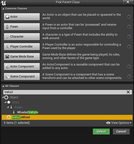
- Expand All Classes tab at the bottom of the class select window
- Search for VehicleWheel class and select it
- We will name it BP_VehicleWheel you can name as you want, just remember its name
We need to adjust wheel sizes in BP_VehicleWheel blueprint, so it would match our vehicle wheel sizes.
- Open BP_VehicleWheel blueprint
- Look in Details tab under Wheel section
- There change Shape Radius to 50 or your own value
- Also, change Shape Width to 20 or your own value
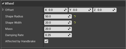
If you don't know what are your wheel sizes, you can go back to blender and check them there. We already had a look at how to check them. Just remember that Shape Width actually is a half-width of the wheel.
Animation blueprint creation
Before we make vehicle blueprint, we will make animation blueprint for it.
- Click Add new button or right mouse click in the content browser
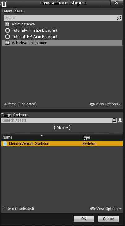
- Under Create Advanced Asset move to Animation and in a sub-menu select Animation Blueprint
- In Create Animation Blueprint window as Parent Class select VehicleAnimInstance
- In the same window as Target Skeleton select your vehicle's skeleton.
- Press OK
- We will name it ABP_VehicleAnimation
To have our animation blueprint useful, we need to add some things in its Anim Graph.
- Open ABP_VehicleAnimation
- In the left bottom side we can see Graphs section, there we double click on Anim Graph to open it
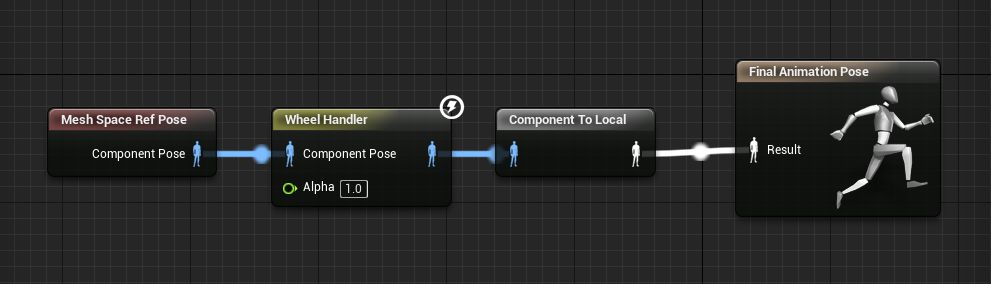
- In open Anim Graph we will see Final Animation Pose node
- Right click on an empty space in the graph and find Wheel Handler for WheeledVehicle and select it
- Connect Wheel Handler node's right side output with Final Animation Pose Result input, a new node will appear between their connection named Component To Local
- Right click on the empty space in the graph and find Mesh Space Ref Pose and select it
- Connect Mesh Space Ref Pose with Wheel Handler Component Pose input
- Save it and you are now done with this blueprint
Input setting setup
Before we create our vehicle blueprint, it would be nice to bind inputs to our project, so we could make straight away playable vehicle, so we would not need in the middle of blueprints creation go out of it and bind inputs to the project.
- Open Project Settings, you can find them under Edit menu or Settings menu over the game viewport
- In the left side of Project Settings window open Input tab
- Expands Axis Mapping and add mapping for:
- Forward
- TurnRight
- LookUp
- LookRight
- Assign inputs to each mapping like in image below, also remember to assign right scales to them (change 1 to -1 where needed)
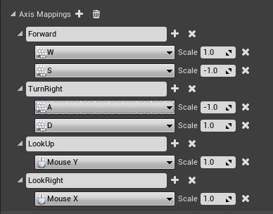
You can choose your own names for axis mappings and your own inputs, just remember their names and what inputs you assigned to each axis.
Vehicle blueprint creation
We have blueprints for wheels and vehicle's animation, now we can make vehicle blueprint.
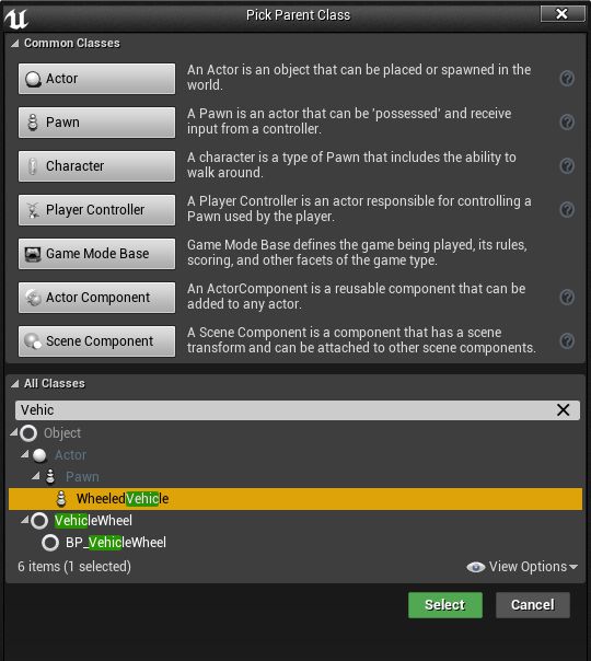
- Click Add new button or right mouse click in the content browser
- Select Blueprint Class
- Expand All Classes tab at the bottom of the class select window
- Search for WheeledVehicle class and select it
- We will name it BP_Vehicle you can name as you want, just remember its name
We want to make sure, that we would automatically posses it, so we could test vehicle right away. So at first we will make our sure, that it's auto possessed by a player.
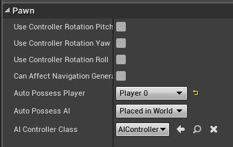
- Open BP_Vehicle
- Open Class Defaults, you can find it in the top middle part of the window.
- In the right side of the window in Details tab under Pawn selection change Auto Posses Player to Player 0
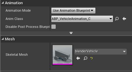
Now we will set up our mesh and it's animations.
- At the left top side of the window we can see Components tab, we select Mesh (inherited) in it
- Now at the right side in the Details tab under Animation section change Anim Class to ABP_VehicleAnimation or however you named your animation blueprint
- In the same Details tab under Mesh section change Skeletal Mesh to our vehicle's mesh
We also need camera attached to our vehicle.
- While in the Components tab Mesh is selected press on Add Component button
- Search for Spring arm in menu and select it
- Select Spring arm in Components tab and again press Add Component button
- Search for Camera in menu and select it
- Select Spring arm again and in the Details tab under Camera section adjust Target Arm Length to your preferred camera distance.
- I set the distance to 1000
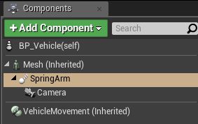
Now we will setup our wheels for the vehicle.
- In Components tab select VehicleMovement (Inherited)
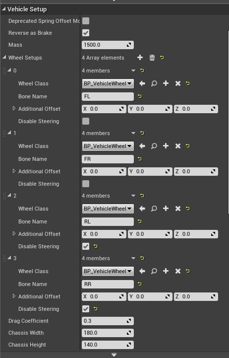
- In Details tab now move to Vehicle Setup section
- Expand Wheel Setups there you will see 4 wheel settings
- For each Wheel Class set BP_VehicleWheel
- Set first two wheel Bone Name to front wheel bone names, in my case they are FL and FR
- Set last two wheel Bone Name to rear wheel bone names, in my case they are RL and RR
- Set last two wheel Disable Steering to checked
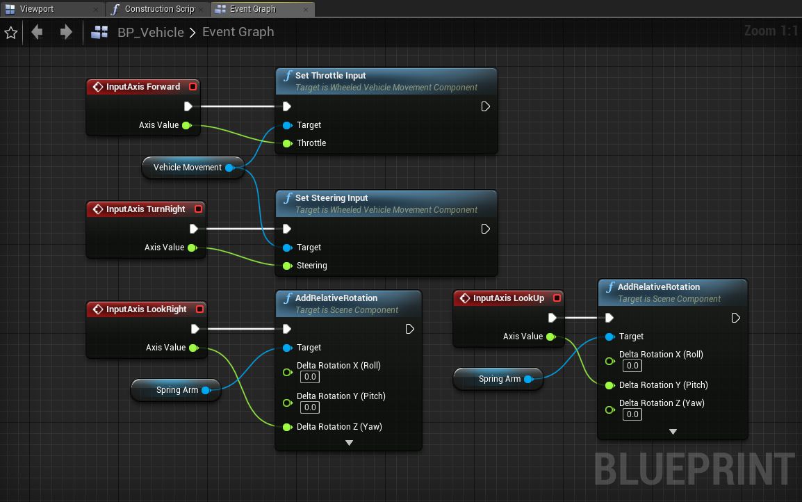
After this we actually could put our vehicle in the level and test if it's holding right on the ground, but we could not ride it or move camera around it. That's why we will set up controls before we put vehicle in level.
- Open Event Graph tab
- In it make following blueprints which you see in image below
- When you will use AddRelativeRotation node, you will not have 3 inputs by default, to get them Right click on Delta Rotation variable and press Split Struct Pin, and now you will have 3 inputs
- After blueprint is done, don't forget to press Compile
Now our vehicle should be done and we can drag it in our level and it should be ready to drive. Just hit Play and we should be able to ride around with it and move camera around the vehicle with a mouse.
For debug
There is still possibility that we may have did something wrong. So there is good thing to know how to debug and look what's wrong with our vehicle.
- After you pressed Play Press ` (tilde '~' key) to open console and then type in it pxvis collision and hit enter. Now you can see physics collisions.
- If you will press F8 while you in game, you will unposses your controlled pawn, and you can freely move around your vehicle and check if everything with collisions or wheels is fine.
Share on
Related Creations
Related Articles
How to get simple suspension animation for vehicle in UE4 with Blender 2.8
Tutorials Blender Unreal Engine
How to get simple physics simulation animation from Blender 2.8 to UE4
Tutorials Blender Unreal Engine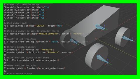
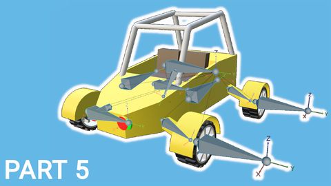
Rigging the vehicle model in Blender | [Part 5] Low poly vehicle for UE4
Tutorials Blender Unreal Engine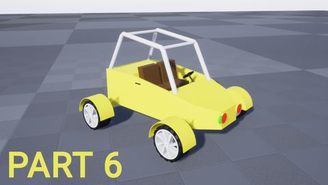
Setting up basic vehicle in Unreal Engine 4 | [Part 6] Low poly vehicle for UE4
Tutorials Unreal Engine
Making openable doors and animated steering wheel | [Part 8] Low poly vehicle for UE4
Tutorials Unreal Engine
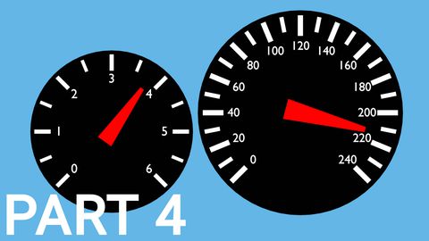
Adding speedometer and tachometer and 1st person camera | [Part 10] Low poly vehicle for UE4
Tutorials Unreal Engine
Adding turn signals with automatic turn off | [Part 11] Low poly vehicle for UE4
Tutorials Unreal Engine