Modeling low poly vehicle wheels in Blender | [Part 2] Low poly vehicle for UE4
by Arthur Ontuzhan
Posted 6 years, 5 months ago Last edit 2 years, 3 months ago
Categories: Tutorials Blender Tags: Vehicle Blender 2.8
Table of contents
Introduction
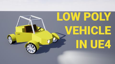
This is the second part of the tutorial series on how to create a low poly vehicle for Unreal Engine 4 using Blender and other free software. You can see the outcome of the tutorial series or get project files here.
In this tutorial, we will model low-poly vehicle wheels in Blender. I will use Blender 2.81, but newer versions also should work.
You can find other parts here:
- [Part 1] Modeling low poly vehicle base in Blender.
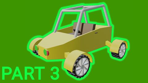
- [Part 3] Texturing the vehicle model.
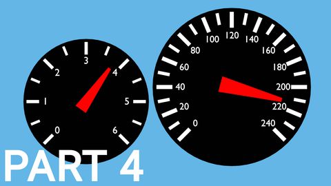
- [Part 4] Making speedometer and tachometer textures.
- [Part 5] Rigging vehicle the vehicle model.
- [Part 6] Setting up basic vehicle in Unreal Engine 4.
- [Part 7] Making mudguards and brake calipers move together with wheels.
- [Part 8] Making openable doors and animated steering wheel.
- [Part 9] Adding lights and brake lights.
- [Part 10] Adding speedometer and tachometer and first person camera.
- [Part 11] Adding turn signals with automatic turn off.
- [Part 12] Generating and setting up basic engine sounds.
Also, there's a video if you have difficulties to understand some parts.
Modeling
Modeling wheel
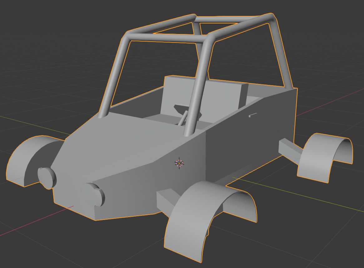
If you have completed the previous tutorial, you should have a vehicle base which looks like in the image below. Well, it will be hidden pretty much the whole tutorial.
At first, we will add Circle mesh from which we will model out a wheel and an empty which will help with one modifier.
- Select the vehicle mesh and hide it by pressing H (press Alt+H to unhide hidden objects).
- Add Circle mesh - press Shift + A and then in Mesh sub-menu select Circle.
- In the Add Circle widget set its Radius to 0.3 m and Vertices to 32.
- Add Empty object - press Shift + A and then in Empty sub-menu select Plain Axes.
- Select Empty object and set its Z rotation to 45 degrees. Rotation will help us with the array modifier later.
- Switch view to Top Orthographic view - Num 7.
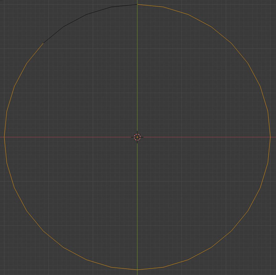
- Select circle mesh and go into edit mode Tab.
- Select 1/8 of the circle, that is 4 edges if your circle has 32 vertices.
- Invert selection - press Ctrl+ I. In the image below you should see how selection should look at the end
- Delete selected edges - press X and select Edges.
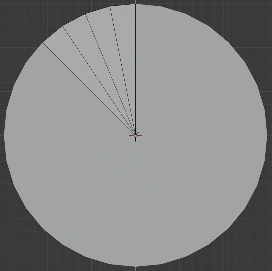
Now we should have 1/8 of the circle. We will use an array modifier now, to get back circle. It might seem stupid, but it will save us time on creating a base for the wheel.
- Add the Array Modifier to the mesh.
- Set Count to 8.
- Uncheck Relative Offset.
- Check Object Offset.
- Select Empty as the object for offset.
You should now see full circle again. If it is still 1/8 of the circle, then check if you have rotated empty 45 degrees on Z-axis.
- Make sure that Transform Pivot Point is set to the 3D cursor and 3D cursor is in the center of the circle.
- In the Edit mode select circle edges.
- Extrude edges and then scale them to 0 - Press E then S and type 0 and accept action by left mouse click or pressing Enter.
We have filled circle now. Now we will divide it into segments by using loop cuts.
- Hover the mouse cursor over faces and add loop cut by pressing Ctrl+ R.
- Accept loop count by left mouse click or pressing Enter and accept loop location by left mouse click or pressing Enter
- While the loop is selected, scale it by 1.8. Press S and type 1.8 and accept action by left mouse click or pressing Enter. Make sure that Transform Pivot Point is set to the 3D cursor.
- Now in the inner piece of circle add another edge loop and scale it again by 1.8 like in the previous step.
- Again in the inner piece of circle add edge loop and scale it by 0.5.
- Select the biggest segment faces. You can see how it should look in the image below.
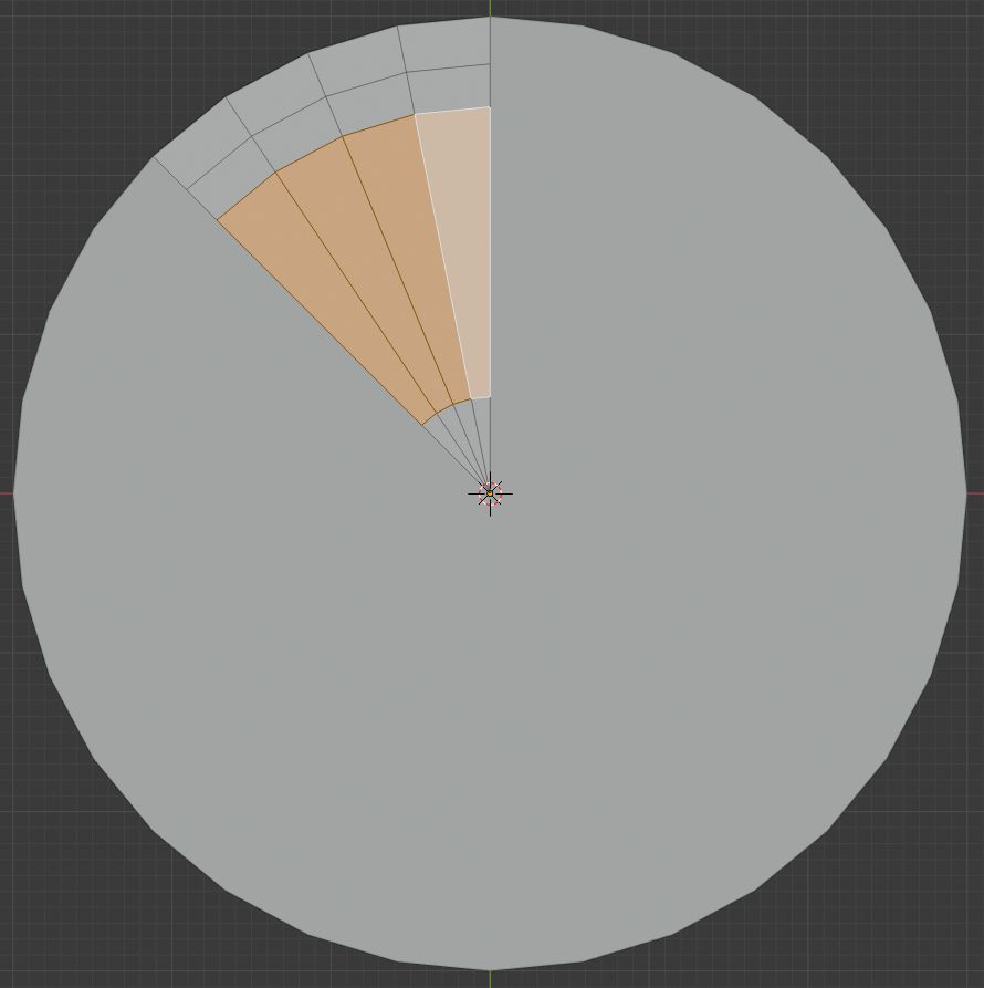
- Delete previously selected faces - Press X and select Faces.
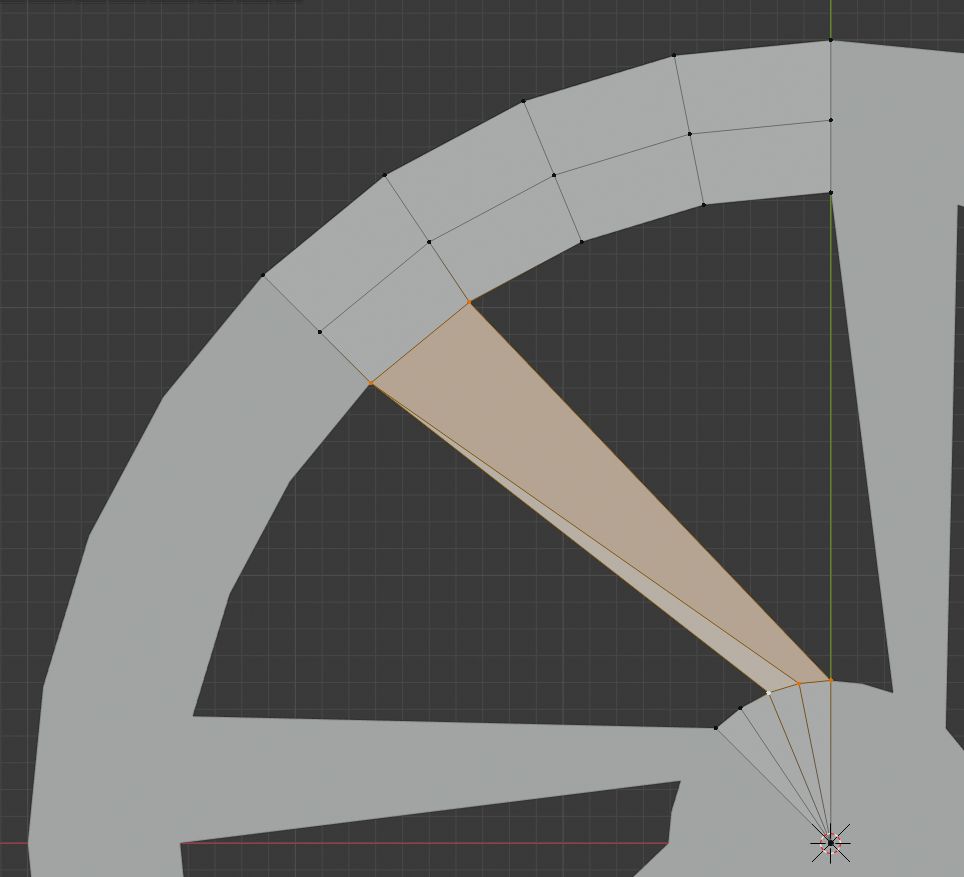
- Now between segments make 2 connected faces by selecting vertices and making face by pressing F. Look in the image below to see how faces should be placed. For more detailed information, you can look in the video.
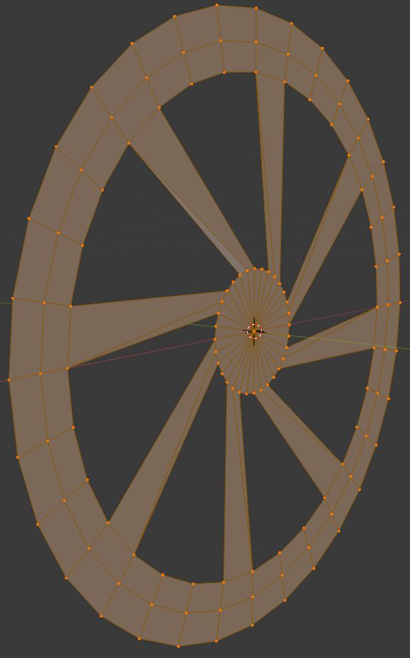
- Go to object mode - Tab.
- Apply Array Modifier - press the Apply button in the modifier panel.
- Go to edit mode - Tab.
- Select all vertices by pressing A.
- Merge duplicate vertices - Press Alt+M and in the menu select By Distance.
- While all vertices are selected rotate mesh around X-axis by 90 degrees - Press R and type 90 and accept action by left mouse click or pressing Enter.
Now we can our 2D plane make into a 3D object.
- While the whole object is selected, extrude it by 0.1 - Press E and type 0.1 and accept action by left mouse click or pressing Enter.
- On extruded face select only 2 outer rows with faces and extrude again by 0.2 - Select faces, press E and type 0.2 and accept action by left mouse click or pressing Enter.
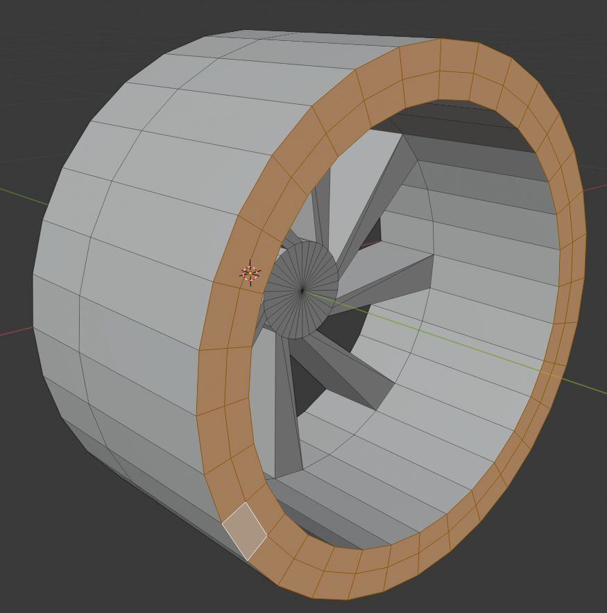
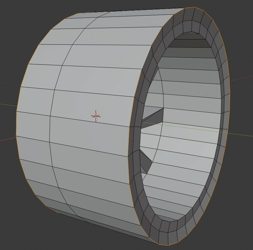
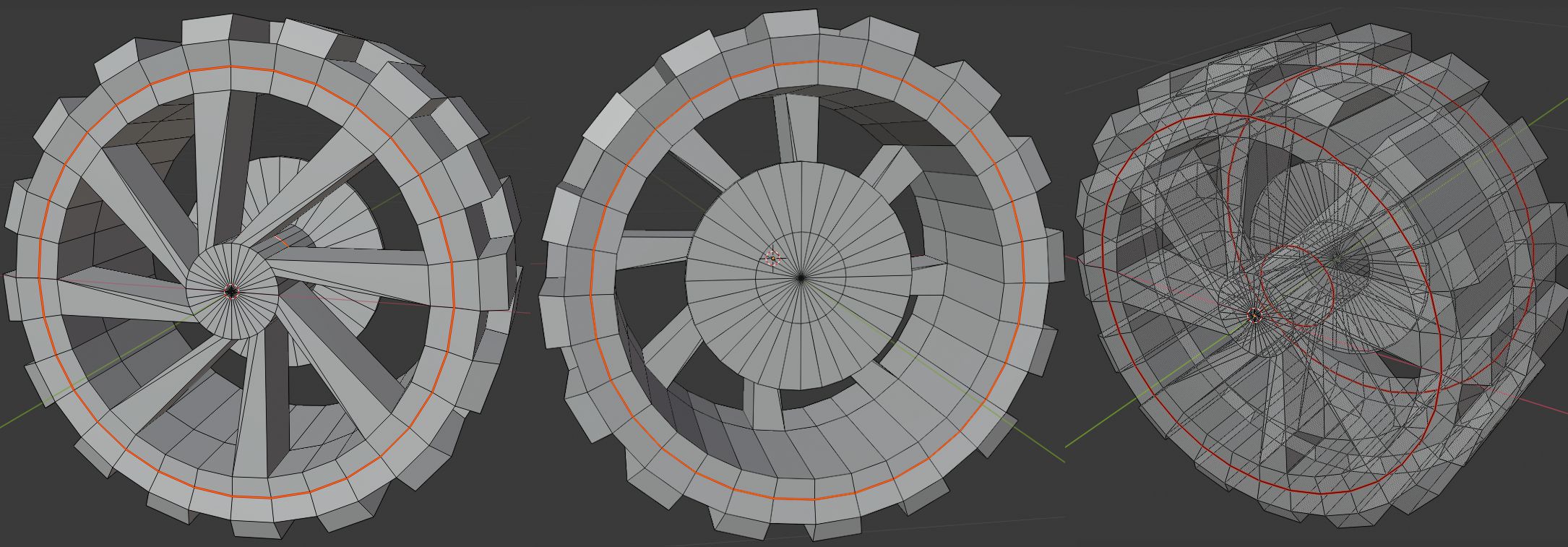
Now we have a cylinder-like shape object.
- Select outer circle edge loops on both sides. Look in the image below to understand more.
- Set Transform Pivot Point to Bounding Box Center.
- Scale edge loops by 1.05 on Y-axis - Press S and then press Y and type 1.05 and accept action by left mouse click or pressing Enter.
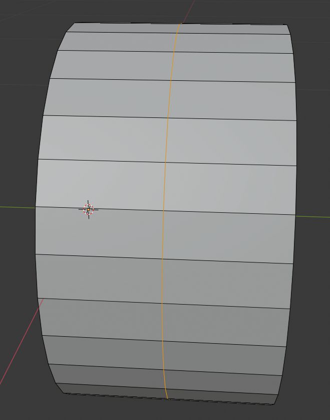
We have one edge loop at the outside of the wheel mesh. We need to move it to the center of the object. We could try to eyeball the center and move it by hand or calculate by how much we need to move it, but I think the faster and more precise way is just to dissolve the middle edge loop and then add a new edge loop, which will automatically set on the middle of the mesh.
- Select middle edge loop - Hold down Alt and click on one of the loop edges.
- Dissolve edges - Press X and select Dissolve Edges.
- Add edge loop - Hover over mesh with the mouse cursor and press Ctrl + R, then accept action by left mouse click or pressing Enter and cancel edge loop move by pressing right mouse click or Esc.
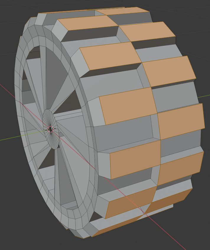
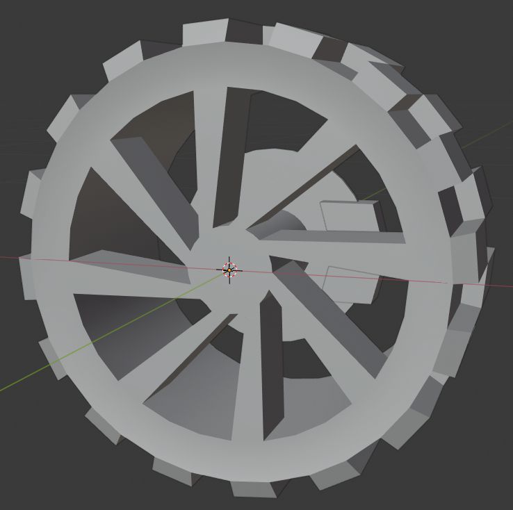
- Select faces around the wheel.
- In the Select menu select Checker Deselect.
- Extrude selected faces out from the mesh center - Press E then S and then Shift+Y and type 1.1 and accept action by left mouse click or pressing Enter.
- While our extruded faces are still selected, scale them on Y-axis by 0.9 - Press S then Y and type 0.9 and accept action by left mouse click or pressing Enter.
Adding brake disc
We have our wheel done. Now we will add really stylized and simple brake disc.
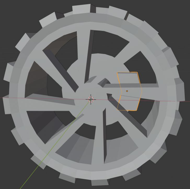
- Select inside wheel faces that assemble a small circle. Look in the image below.
- Extrude by 0.1 - Press E and type 0.1 and accept action by left mouse click or pressing Enter.
- Extrude again by 0.01 - Press E and type 0.01 and accept action by left mouse click or pressing Enter.
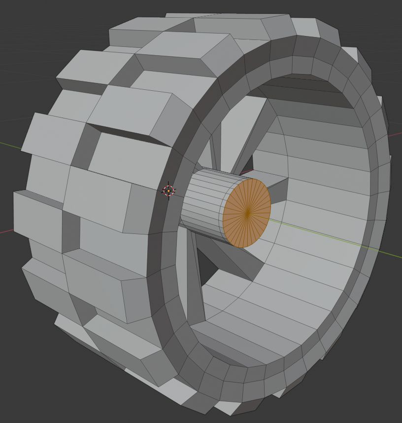
- Select the face loop at the end of the previously extruded cylinder.
- Extrude faces outwards - Press E then S and then Shift+Y and type 2.5 and accept action by left mouse click or pressing Enter.

Adding brake caliper
We will not add brake caliper to the wheel mesh, we will make it as additional object, because later we will add it to our vehicle base mesh.
- Exit edit mode - Tab.
- Add Cube mesh - press Shift + A and then in Mesh sub-menu select Cube.
- Change its dimensions to X 0.08 m, Y 0.05 m, Z 0.15 m.
- Enter edit mode - Tab.
- Add horizontal loop cut - Hover over mesh with the mouse cursor and press Ctrl + R, then accept action by left mouse click or pressing Enter and cancel edge loop move by pressing right mouse click or Esc.
- Move loop by -0.02 m on X-axis - Press G then press X and type -0.02 and accept action by left mouse click or pressing Enter.
- Exit edit mode - Tab.
- Set its location to X -0.12 m, Y -0.2 m, Z 0 m.
Now we should see really basic brake caliper on the brake disc in the wheel.
Finalizing wheel
At first, we will set our both mesh shading to smooth and apply Auto Smooth to them.
- In the object mode select both meshes.
- Right-click while the mesh is selected and select Shade Smooth.
- In Object Data Properties tab in Normals section check Auto Smooth. This will add Auto Smooth to just an active object.
- Activate other mesh and repeat the previous step.
Also, we will set the brake caliper's parent to the wheel. It will help with brake caliper placing later when we will duplicate them and move around.
- Select brake caliper and then by holding Shift select wheel.
- Press Ctrl+P and select Object.
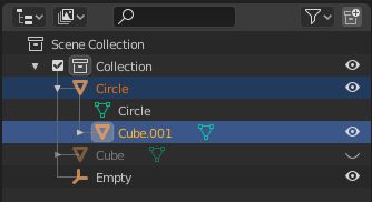
After object parenting, in the Outliner we should see brake caliper cube object under Wheel Circle object as in the image above.
We will not duplicate our wheels now and set them to the vehicle base, because in the next tutorial we will texture our objects, and we don't want to texture 4 wheels when we can texture one and then duplicate it textured.
Share on
Related Creations
Related Articles
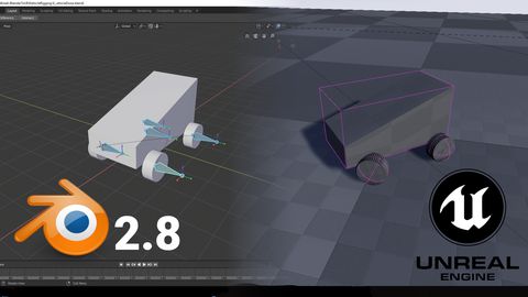
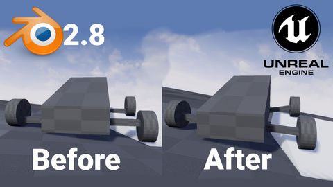
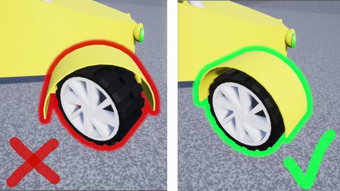
How to get simple suspension animation for vehicle in UE4 with Blender 2.8
Tutorials Blender Unreal Engine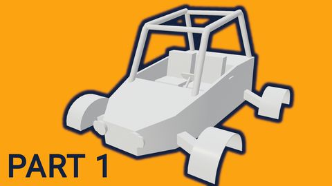
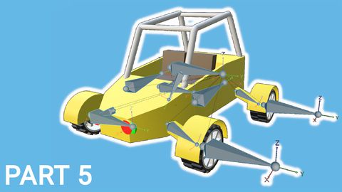
Rigging the vehicle model in Blender | [Part 5] Low poly vehicle for UE4
Tutorials Blender Unreal Engine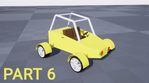
Setting up basic vehicle in Unreal Engine 4 | [Part 6] Low poly vehicle for UE4
Tutorials Unreal Engine
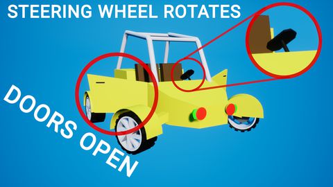
Making openable doors and animated steering wheel | [Part 8] Low poly vehicle for UE4
Tutorials Unreal Engine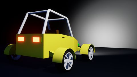
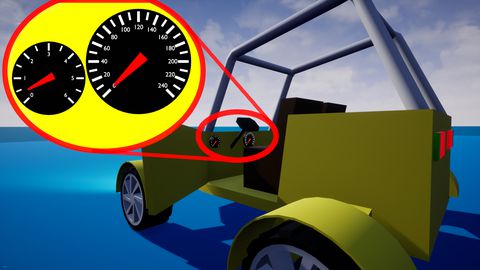
Adding speedometer and tachometer and 1st person camera | [Part 10] Low poly vehicle for UE4
Tutorials Unreal Engine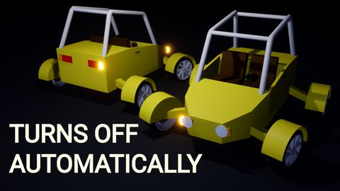
Adding turn signals with automatic turn off | [Part 11] Low poly vehicle for UE4
Tutorials Unreal Engine