Rigging the vehicle model in Blender | [Part 5] Low poly vehicle for UE4
by Arthur Ontuzhan
Posted 6 years, 2 months ago Last edit 2 years, 3 months ago
Categories: Tutorials Blender Unreal Engine Tags: Vehicle Blender 2.8 UE4
Introduction
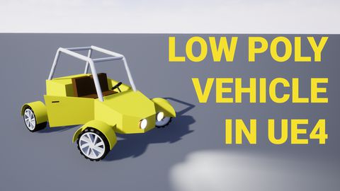
This is the fifth part of the tutorial series on how to create a low poly vehicle for Unreal Engine 4 using Blender and other free software. You can see the outcome of the tutorial series or get project files here.
In this tutorial, we will rig the low-poly vehicle in Blender for Unreal Engine 4. I will use Blender 2.82, but newer versions also should work.
You can find other parts here:
- [Part 1] Modeling low poly vehicle base in Blender.
- [Part 2] Modeling low poly vehicle wheels.
- [Part 3] Texturing the vehicle model.
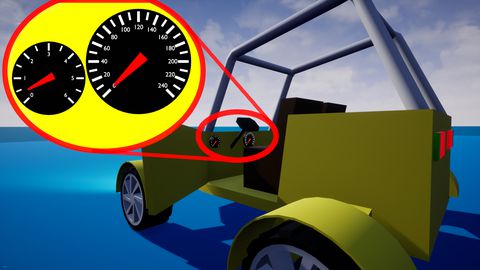
- [Part 4] Making speedometer and tachometer textures.
- [Part 6] Setting up basic vehicle in Unreal Engine 4.
- [Part 7] Making mudguards and brake calipers move together with wheels.
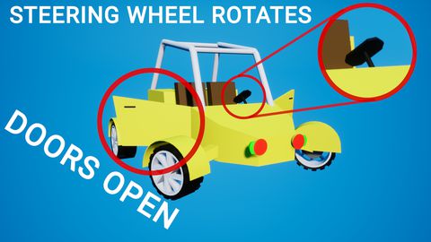
- [Part 8] Making openable doors and animated steering wheel.
- [Part 9] Adding lights and brake lights.
- [Part 10] Adding speedometer and tachometer and first person camera.
- [Part 11] Adding turn signals with automatic turn off.
- [Part 12] Generating and setting up basic engine sounds.
Also, there's a video if you have difficulties to understand some parts.
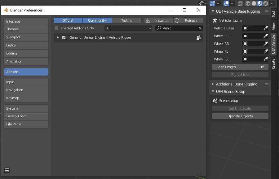
If you followed all the steps, you should see the addon checked in the Blender's addon list and when you press N key in the 3D viewport, you should see a new section in the properties menu.
Basic vehicle rig
To get basic rig for vehicle with the addon doesn't require much time.
- Open the rigging addon menu by pressing N key and open UE4 vehicle tab.
- With object pickers pick objects in viewport or select them from the list.
- Vehicle Base - Is vehicle model without wheels.
- Wheel FR - Front Right wheel.
- Wheel RR - Rear Right wheel.
- Wheel FL - Front Left wheel.
- Wheel RL - Rear Left wheel.
- After you have selected all parts you should see Rig Vehicle button enabled - press it.
- Your vehicle base rig is done. You should end up in the pose mode, where you can test if vehicle is rigged correctly.
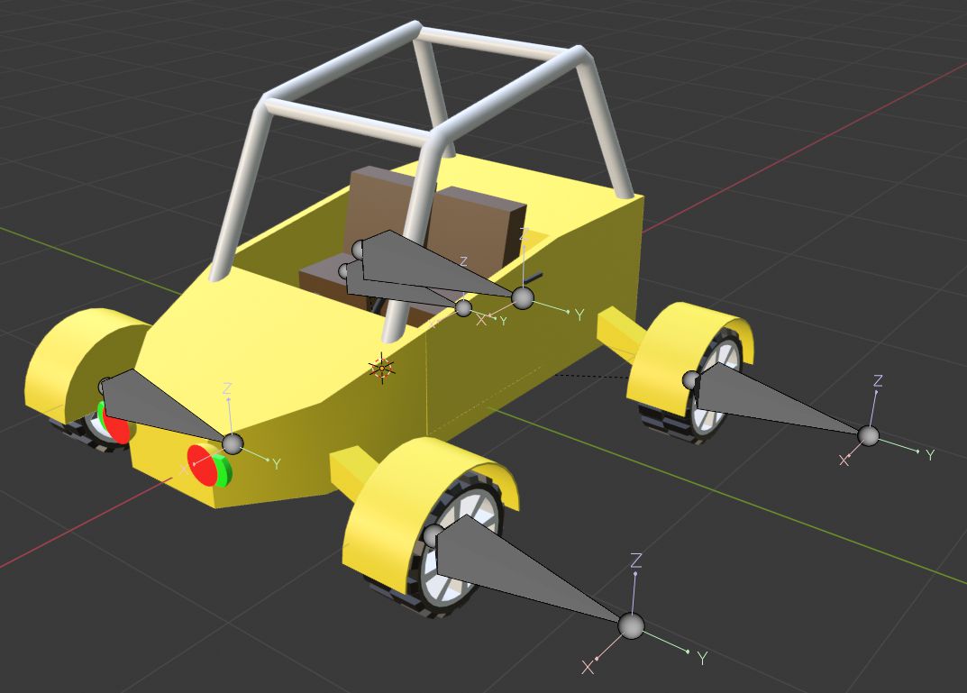
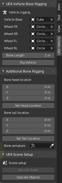
Now we need to set our Bone Head location and Bone Tail location. We can do that by entering values manually, or by using Set Location buttons that will set locations to our selections in edit mode. This time we will use the second method.
- Go into object mode and select vehicle base mesh.
- Enter edit mode Tab.
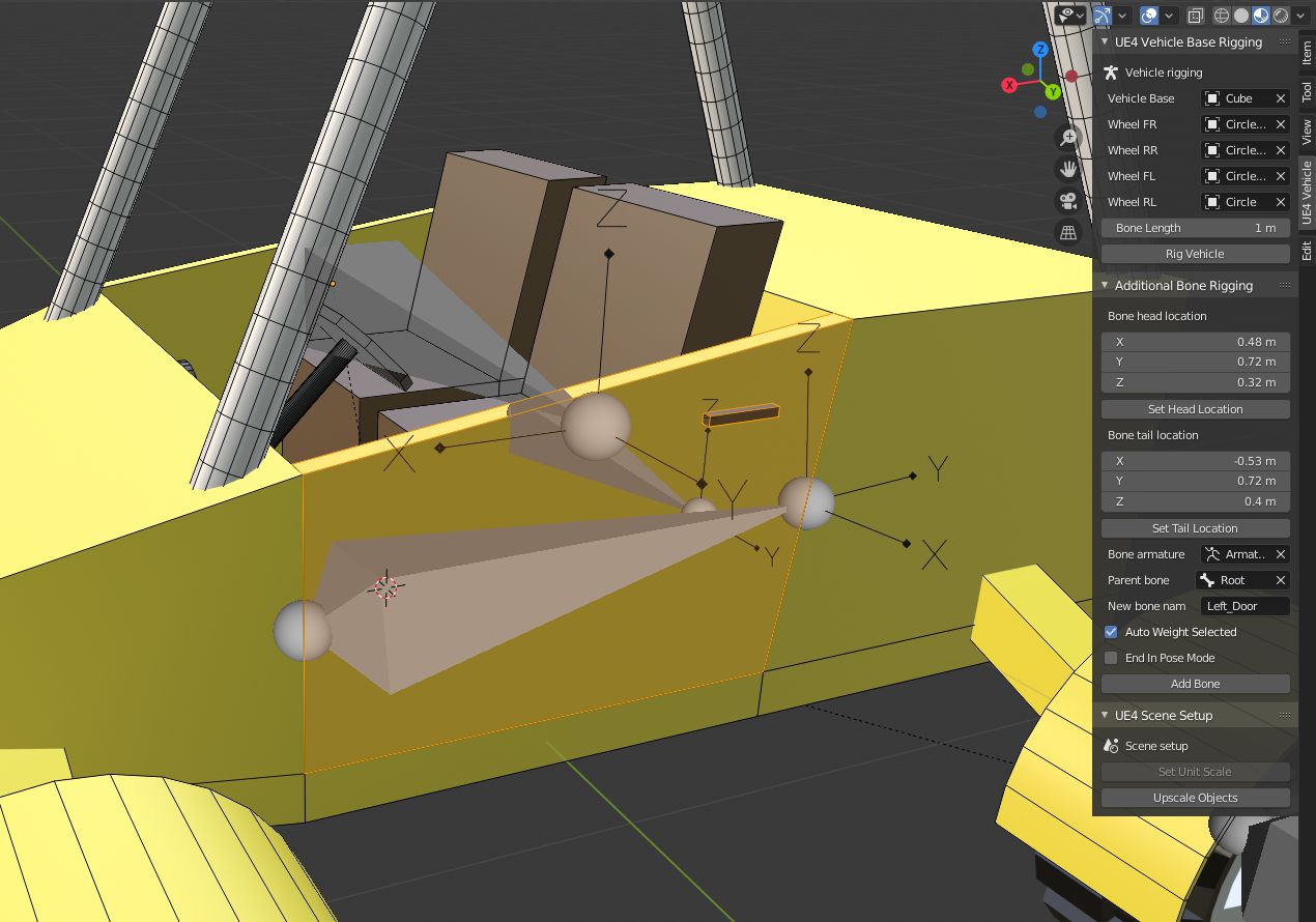
- Select only door's outer front side edge - Watch the image below.
- Press Set Head Location button.
- Select only door's outer rear side edge - Watch the image below.
- Press Set Tail Location button.

You should see similar head and tail values as in the image above. It depends on which side doors you chose to rig first.
- Select door and door handle mesh - Use L to make mesh part selection faster.
- In the Bone Armature value set vehicle armature.
- Set Parent Bone to our Root bone.
- Set how new bone will be named. I used Left_Door and Right_Door for door names.
- Click on the Add Bone button.
For the second door do the same steps:
- Set new Head and Tail locations.
- Select second door and door handle meshes.
- Give a new bone name.
- Press the Add Bone button.
- Also, if you want to check in pose mode if doors got rigged correctly, before pressing Add Bone button check End in Pose Mode checkbox. After adding the bone it will automatically set you to pose mode.
Rigging steering wheel
The steering wheel will be rigged in the same way as our doors were. But this time we will just select steering wheel faces for bone head and tail locations.
- Select steering wheel's top face -Watch the image below.
- Press Set Head Location button.
- Select steering wheel's bottom face. Enable X-Ray to see that face. Watch the image below.
- Press Set Tail Location button.
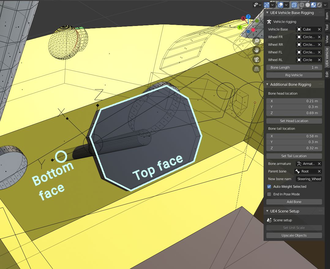
You should see similar head and tail values as in the image above.
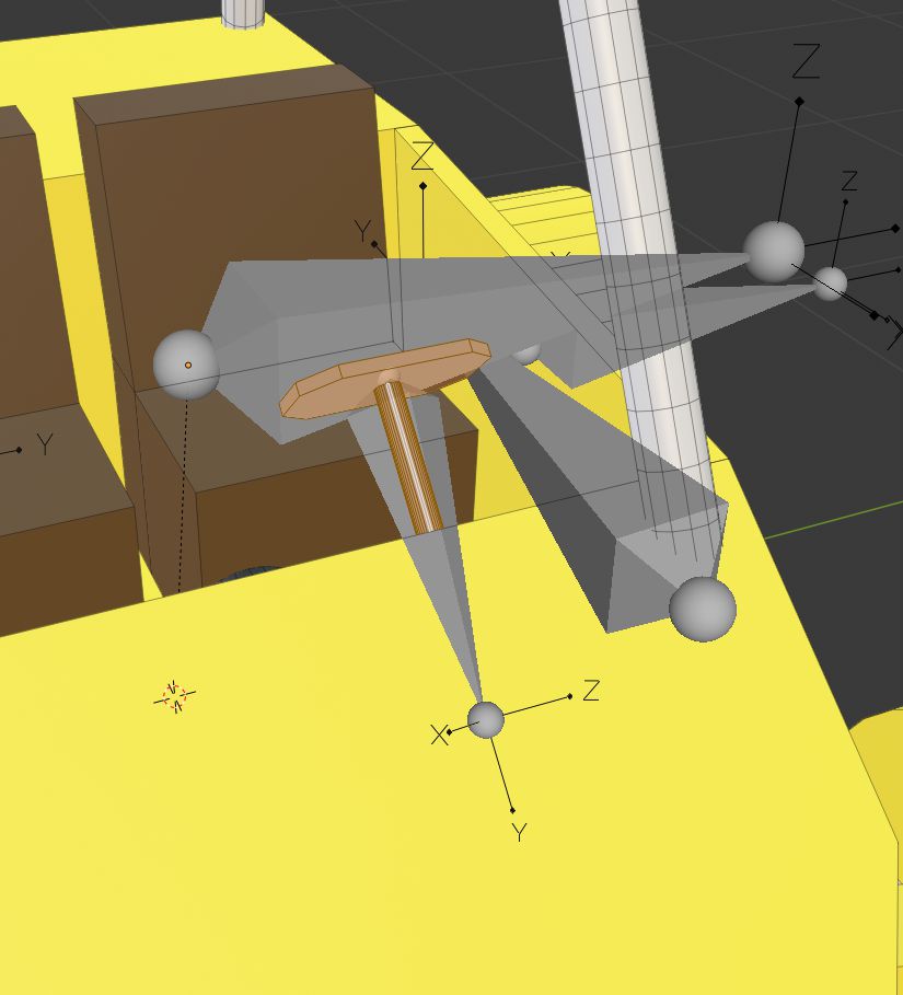
- Select both steering wheel's meshes - Use L to make mesh part selection faster.
- Change what will be a bone name. I set it to Steering_Wheel.
- Click on the Add Bone button.
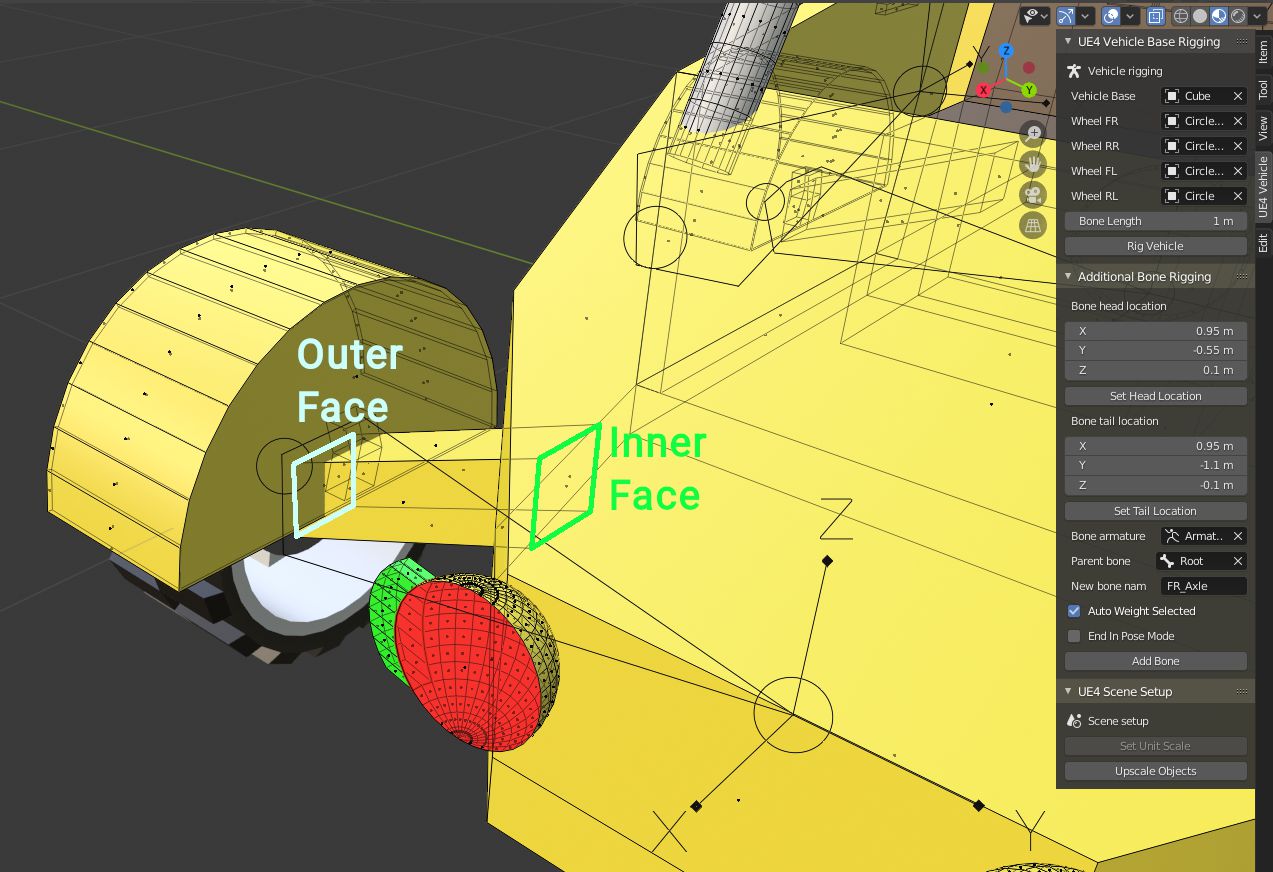
In the image above I have selected Front Right Axle. You should get similar values for head and tail.
- Select axle mesh - Use L to make mesh part selection faster.
- Change what will be a bone name. I used these names for my axles: RL_Axle, RR_Axle, FR_Axle, FL_Axle.
- Click on the Add Bone button.
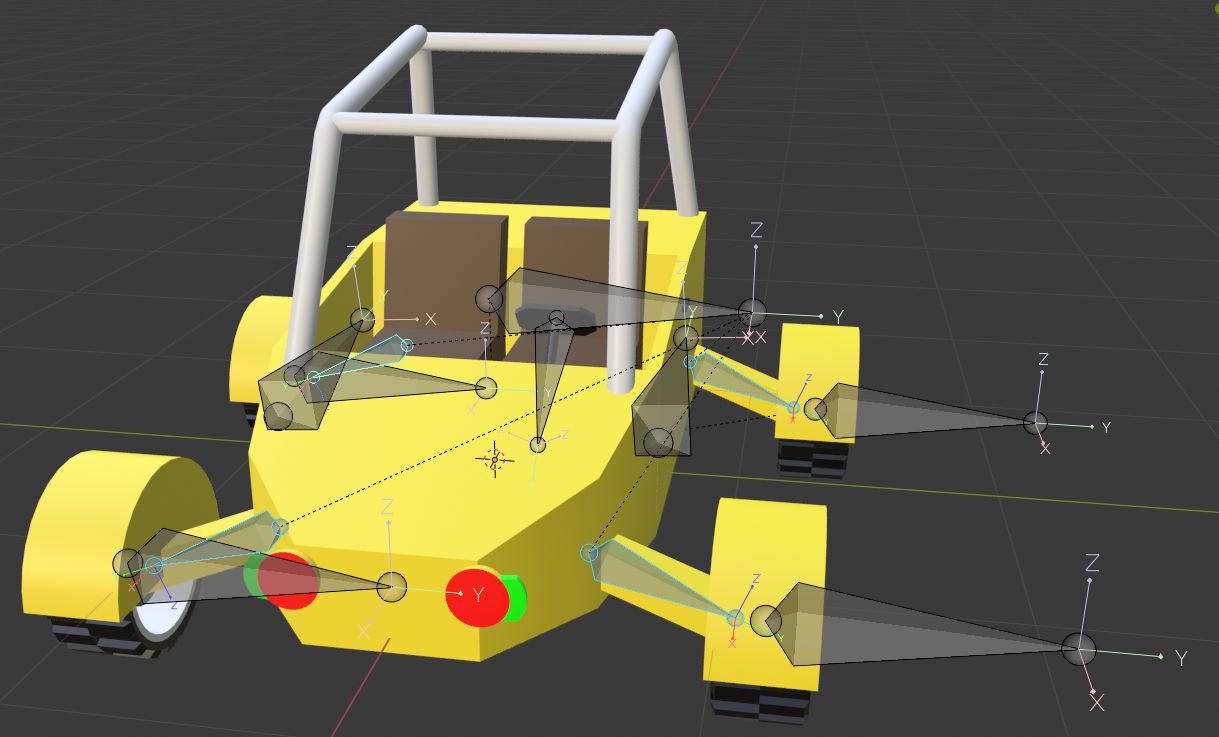
Repeat the same steps for each axle.
Adding duplicate wheel bones
We will need to add some additional bones for our wheels and rig them manually, so our wheel mudguards and brake calipers would turn together with wheels.
- Into Object mode select armature.
- Enter into edit mode - Tab.
- Select all four wheel bones.
- Duplicate them by pressing Shift + D.
- Into Outliner find newly duplicated bones and select them.
- Press Ctrl+F2.
- Into newly opened Batch Rename widget set Data Type to Bones.
- Into find field type .001.
- Into replace field type _Double.
- Press the OK button.

Now we have made new bones and using batch renaming we renamed them to names which makes more sense to us. Now we need to assign bones to mesh vertex groups.
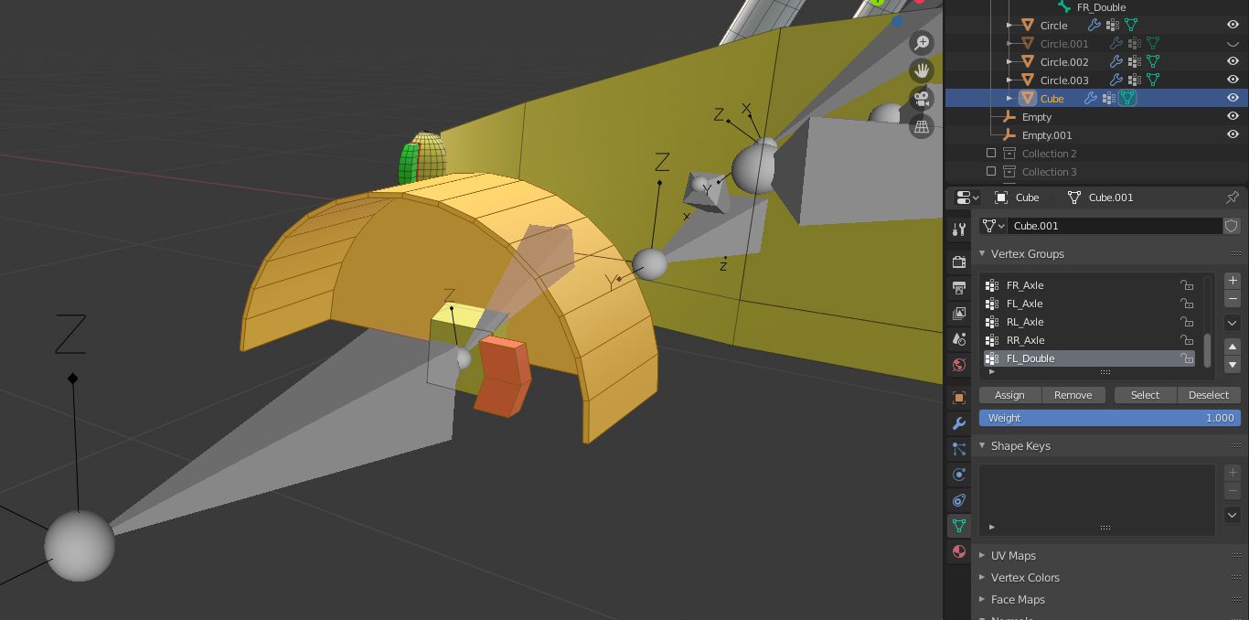
- Into object mode select the vehicle base mesh.
- Enter into edit mode - Tab.
- Select one mudguard and brake caliper mesh. See in the image below (I hide the wheel mesh so could show better) Use L to make mesh part selection faster.
- Into Object Data Properties in Vertex Groups section select Root and press Remove button.
- Into Object Data Properties press + button in Vertex Groups section.
- Rename the new Vertex Group to the correct wheel duplicate bone name.
- Click the Assign button.
- Repeat the same thing for other duplicate bones.
Now you can go to armature pose mode, and check if each wheel double bone moves its own mudguard and brake caliper.
Exporting model
Before exporting the model, we need to check if our model normals are right. After parenting mesh to bones, some of our mesh normals might have flipped. You can find how to do that here.
After that is done, we can export our model.
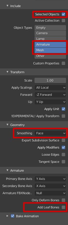
- Go into object mode.
- Make sure that only the vehicle model and armature collection is enabled.
- Select all meshes and armature by pressing A.
- Go to File -> Export -> FBX (.fbx).
- In the export settings check Selected Objects.
- Select only to export Armature and Mesh object types.
- Set Smoothing to Face.
- Uncheck Add Leaf Bones.
- Choose where you want to save your model and press Export FBX button.
Share on
Related Creations
Related Articles
How to get simple suspension animation for vehicle in UE4 with Blender 2.8
Tutorials Blender Unreal Engine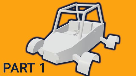
Setting up basic vehicle in Unreal Engine 4 | [Part 6] Low poly vehicle for UE4
Tutorials Unreal Engine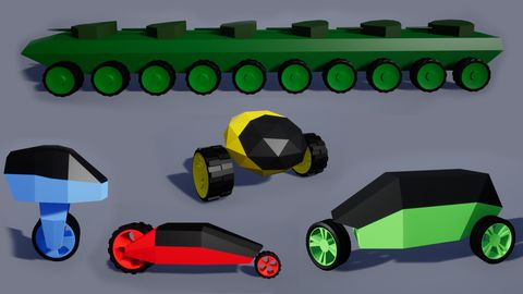
Making openable doors and animated steering wheel | [Part 8] Low poly vehicle for UE4
Tutorials Unreal Engine
Adding speedometer and tachometer and 1st person camera | [Part 10] Low poly vehicle for UE4
Tutorials Unreal Engine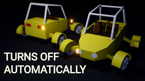
Adding turn signals with automatic turn off | [Part 11] Low poly vehicle for UE4
Tutorials Unreal Engine