Adding speedometer and tachometer and 1st person camera | [Part 10] Low poly vehicle for UE4
by Arthur Ontuzhan
Posted 5 years, 8 months ago Last edit 2 years, 3 months ago
Categories: Tutorials Unreal Engine Tags: Vehicle UE4
Introduction
This is the tenth part of the tutorial series on how to create a low poly vehicle for Unreal Engine 4 using Blender and other free software. You can see the outcome of the tutorial series or get project files here.
In this tutorial, we will add a speedometer and tachometer and first-person camera to the vehicle.
You can find other parts here:
- [Part 1] Modeling low poly vehicle base in Blender.
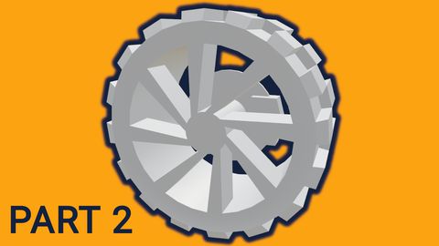
- [Part 2] Modeling low poly vehicle wheels.
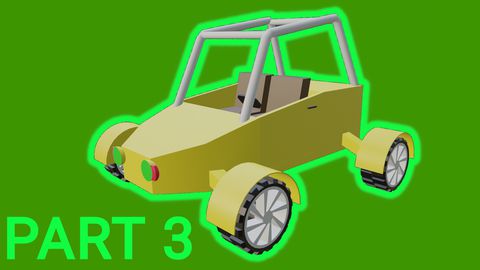
- [Part 3] Texturing the vehicle model.
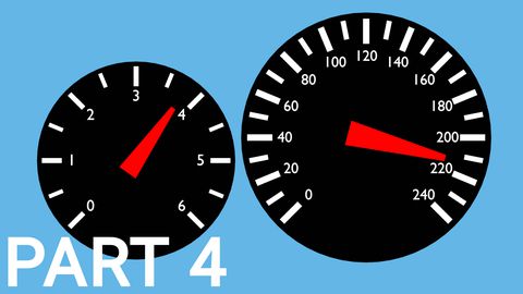
- [Part 4] Making speedometer and tachometer textures.
- [Part 5] Rigging vehicle the vehicle model.
- [Part 6] Setting up basic vehicle in Unreal Engine 4.
- [Part 7] Making mudguards and brake calipers move together with wheels.
- [Part 8] Making openable doors and animated steering wheel.
- [Part 9] Adding lights and brake lights.
- [Part 11] Adding turn signals with automatic turn off.
- [Part 12] Generating and setting up basic engine sounds.
Also, there's a video if you have difficulties to understand some parts.
Making materials for speedometer and tachometer
We will have speedometer and tachometer as UI elements and we will also make them visible in the vehicle's interior.
At first, we need to import speedometer and tachometer textures which we made in one of the previous tutorials.
- Go to Textures folder.
- Press the Import button.
- Select all texture files and click Open.
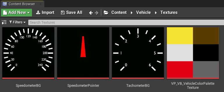
Now in the textures folder you should have 3 new textures: Speedometer face, Tachometer face and a Pointer texture.
Now we have all assets to create our materials.
- Go to the Material folder.
- Create new material there and name it M_Speedometer or whatever you like.
- In new material make blueprints like in the image below.
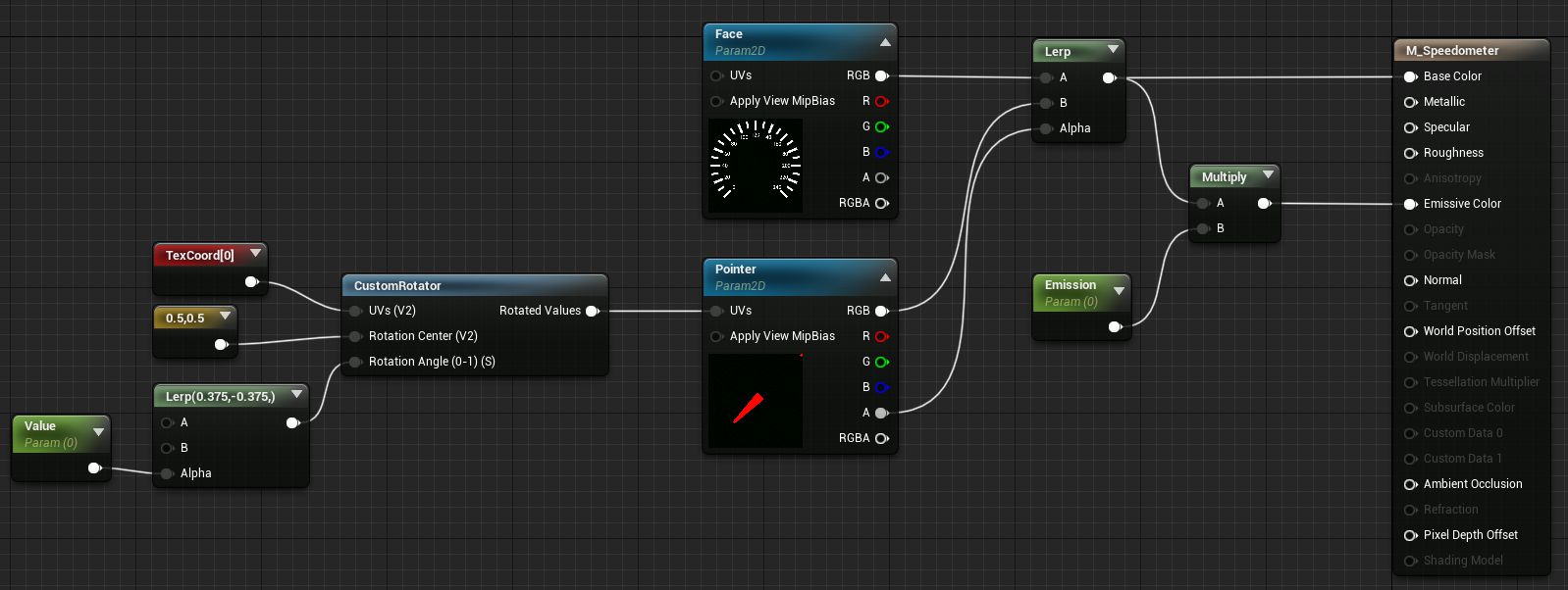
In this material we have 4 parameter values: Face, Pointer, Emission and Value.
We are placing Pointer texture over Face texture using the Lerp node. Lerp (Linear Interpolation) node takes A and B values and then blends them together by using the Alpha value. In this case, A value is Face texture and B value is Pointer texture. As the Alpha value we are using Pointer texture's Alpha values. If Alpha value is 0, we output A value, if it's 1 - we output B value, if It's in between - we blend between both values. Our Pointer texture's background is fully transparent, and in Alpha values it is 0, and the non-transparent part is 1 in Alpha values. So as final output we get Pointer texture over Face texture.
This combination of textures we are setting as material's Base Color and we are also multiplying it with the Emission parameter's value and setting it as material's Emission Color, so we could emulate speedometers or tachometers backlight by changing our Emission value.
To rotate our pointer texture, we are using the CustomRotator node. We have set its UVs input to Texture Coordinates, Rotation Center is set to 0.5, 0.5 so our rotation center would be in the center of our texture. And for the Rotation Angle we are using our Value parameter's value which is interpolated between 0.375 and -0.375. Why are we using 0.375 value? If we look at our speedometer's face texture, then we can see, that if we would fully divide circle with speedometer's biggest sections, we would get 16 sections. For the Rotation Angle a full 360 degrees turn is equal to value 1. So if we divide 1 by 16 we get 0.0625. So we know that with 0.0625 increments we can rotate our pointer by a big section on our speedometer's face. By default, our pointer looks straight at the top, and it takes 6 speedometer sections to get from the top to minimal or maximal value on the speedometer. 6 multiplied by 0.0625 is equal to 0.375. But why we don't start from negative value? A positive value rotates it counterclockwise and our speedometer's minimal value is at that side.
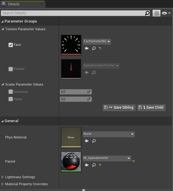
Now from this material we can make a material instance for the tachometer.
- In the content browser right click on the material we just created. I named it as M_Speedometer.
- In the menu select Create Material Instance.
- Rename newly created material instance to MI_Tachometer or whatever you like.
- Open it.
- Set its Face parameter to tachometer's face texture.
Now we have speedometer's and tachometer's materials for the vehicle's mesh done. Now we can open its skeletal mesh asset and set those materials.

But we aren't done with the materials yet. We still need to make separate materials for our User Interface.
- Go to the Material folder.
- Create new material there and name it M_SpeedometerUI or whatever you like.
- Click on the material base node and in details panel change Material Domain to User Interface and set Blend Mode to Masked.
- In new material make blueprints like in the image below.

For this material we changed Material Domain to User Interface so we could use it in the user interface, also we had to switch Blend Mode to Masked so we could use transparency around speedometer and tachometer. Material is doing almost the same thing what our previous one is doing, except we don't have emission in this one and we are using Face texture's alpha as Opacity Mask.
Now from this material we can make a material instance for the tachometer.
- In the content browser right click on the material we just created. I named it as M_SpeedometerUI.
- In the menu select Create Material Instance.
- Rename newly created material instance to MI_TachometerUI or whatever you like.
- Open it.
- Set its Face parameter to tachometer's face texture.

Now we have all materials that we need to set up speedometer and tachometer.
Making a widget blueprint for UI
We need to make a widget blueprint that will be used in our user interface to show speedometer and tachometer.
- Make a new folder named UI. It's placed at the same level as Materials, Meshes and other folders.
- Open UI folder.
- Click Add new button or right mouse click in the content browser.
- Go to the User Interface section and select Widget Blueprint.
- Rename newly created asset to WBP_Speedometer or whatever you like.

- Open the newly created asset.
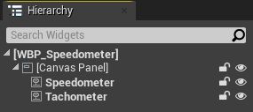
- In the Hierarchy section under Canvas Panel add 2 Image elements as its children. Just pull them in from the Palette section.
- Rename one Image element as Speedometer and another one as Tachometer or name them as whatever you like.
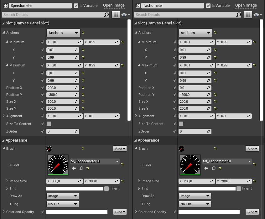
Now for each image element, we need to set its position and what image it will draw. You can see in the image below what settings set for each image we need to set. Make sure you use UI materials for the brush.
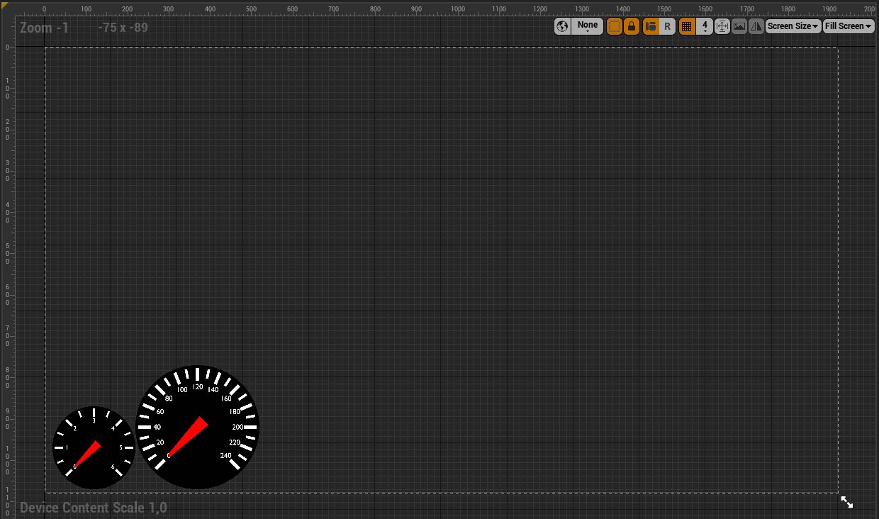
If you set up everything correctly, then you should see in the UI preview window, that on the bottom left side of the viewport you have the tachometer and next to it on the right side there's a bigger speedometer. You can see how it should look in the image below.
We are done with the User Interface visual part, now we need to make a function for it, which would update values for our speedometer and tachometer in it.
- Switch to the Graph view in the Widget Blueprint editor. (Button on the top right side of the editor window)
- Make a new function and name it Update HUD or whatever you like.
- Add 2 float type variables to the function Inputs and name them Speed and RPM or whatever you like.
- In the function make blueprints like in the image below. Make sure that in Set Scalar Parameter Value nodes you set Parameter Name as you have chosen in material blueprints.
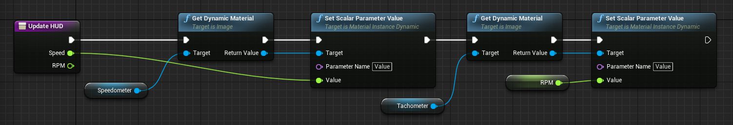
In this function, we take image variables for the speedometer and tachometer and then get the dynamic material out of them. Then we set the value for that material that is responsible for the pointer rotation in the material.
And now we are done with the widget blueprint for our UI.
Setting up speedometer and tachometer in the vehicle blueprint
Now all that's left is to set up our previously created assets in the vehicle's blueprint.
Let's start by creating Dynamic Material Instances for our speedometer and tachometer materials, so we could change their values at the runtime.
- Open ConstructionScript function.
- Make blueprints that you see in the image below. Remember to set correct material indexes.

In the previous tutorial, we have made dynamic material for front and brake lights. This time we are doing the same thing for the speedometer and tachometer: we create dynamic materials and then promote them to variables.
Before using speedometer and tachometer dynamic materials, let's add our previously created widget blueprint to our viewport.
- Find the BeginPlay event in the Event Graph.
- Make blueprints that you see in the image below. Make sure to set correct widget class
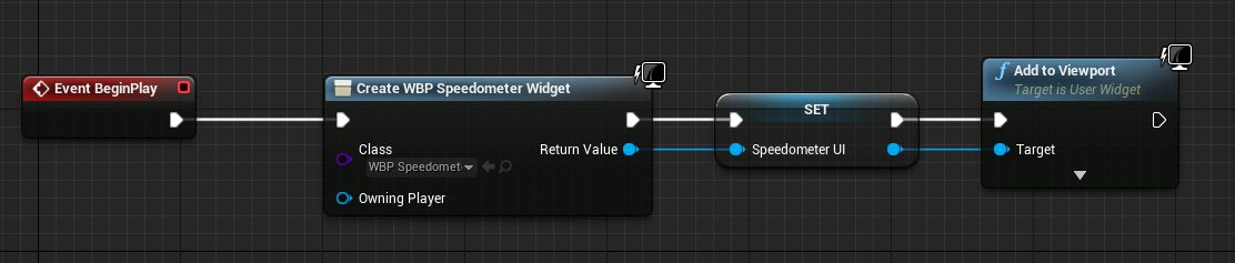
In these blueprints, we are creating a new widget by using our previously created widget blueprint as its class. Then we promote it to variable and then add it to our viewport. Now we should see a speedometer and tachometer in our UI. But you will see that speedometers and tachometers aren't updating their values right now. We will set that up next.
Let's make a function that will update our speedometer and tachometer values. You can see the function in the image below.
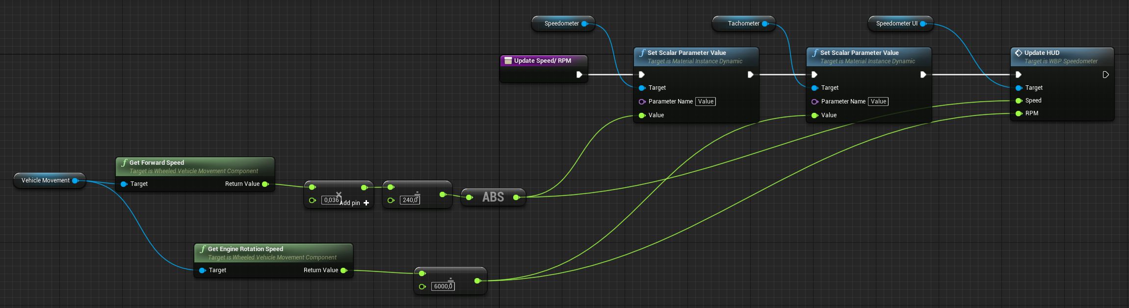
So in this function, we are taking the vehicle's forward speed, then multiplying it by 0.036 and then dividing it by 240 and then making that value absolute and then plugging that value into our speedometer dynamic material value and UI update function. So why do we multiply forward speed value by 0.036? The Forward Speed value is returned in meters per second. To convert that to kilometers per hour, we need to multiply that value by 0.036. You might ask where I got that number? The answer is just google that. If you want to convert that value to miles per hour you need to divide the forward speed value by 44.704. How do I know? Just google that.
Ok. Why do we divide that value with 240? Materials we made for the speedometer and tachometer are set up in that way, that values from 0 to 1 will move the pointer in their min/max region. So to convert km/s value to 0 to 1 value, we just need to divide it by our speedometers maximal value, and in our case, it is 240. And then we just take absolute value from that value, so our speedometer wouldn't try to show negative value when we drive backward.
To get the RPM value, we just get engine rotation speed and then divide it by our max tachometer value, and in our case, it is 6000.
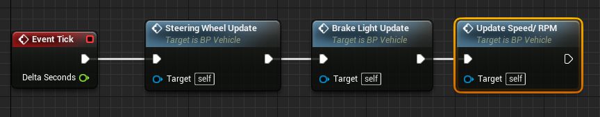
This newly made function also will not work if we will not call it anywhere. So let's hook up to the tick event after our other update functions.
In the previous tutorial, we added an option to turn on and off lights for the vehicle. When we made materials for the speedometer and tachometer, we made an emission value for them, so we could simulate their backlight by changing that value. Let's add a feature to our vehicle, that speedometer's and tachometer's backlight turns on when we turn on our vehicle's lights and turns off when we turn them off.
In the Event Graph find the place where we are turning on and off lights and add the following blueprints to them as in the image below.
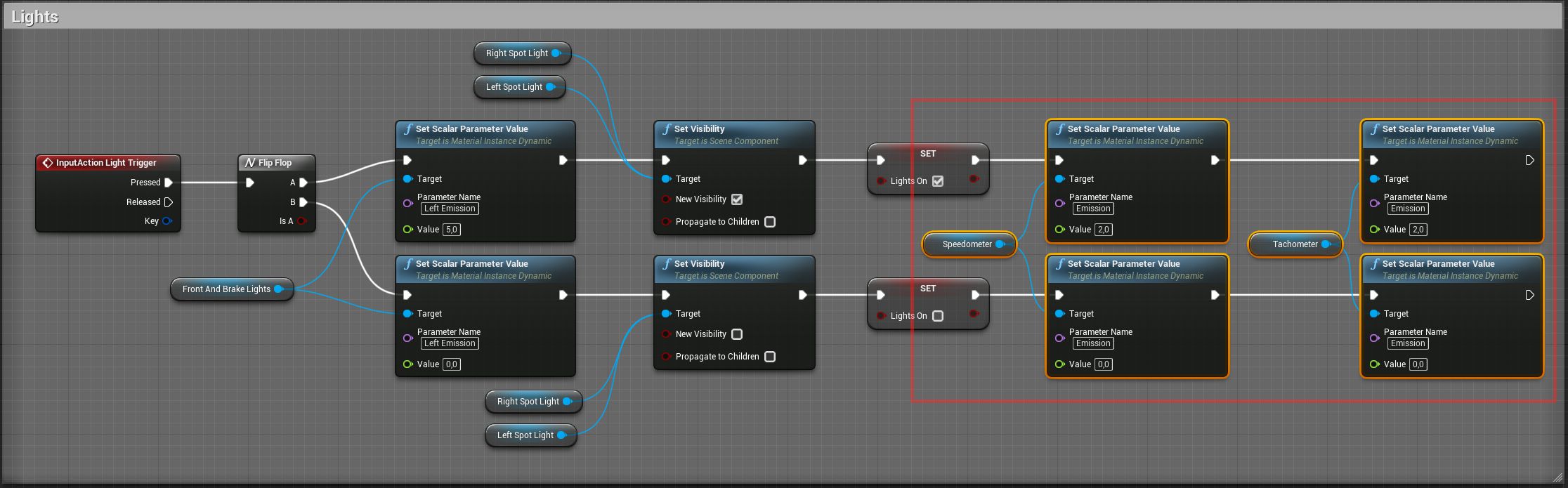
Now you will see that when we turn on lights, the vehicle's speedometer and the tachometer will have a backlight effect.
Setting up a first person camera
We got a speedometer and a tachometer in our vehicle. They also have a backlight feature, but we can't really see what they are showing in them, because the current vehicle's camera is too far from them. Let's add another camera for our vehicle, so we could see what the in-vehicle speedometer and tachometer are showing, and we would also get another view perspective while driving.
Let's start by binding another input that will allow us to switch between our current camera's view and our first-person camera view.
- Open Project Settings.
- Open Input tab and add new Input Bindings as in the image below.
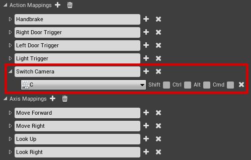
As you can see, I chose the C key for camera switching. Choose your own key that feels right for you.
Now we need to add another camera in our vehicle blueprint, so we would have a camera to switch to.
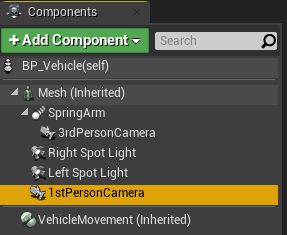
- Under the Mesh component, add a Camera component as a child.
- Rename a new camera to 1stPersonCamera and our old one to 3rdPersonCamera. Also optional step.
Right now our first-person camera's placement isn't great, let's fix that and also do some other changes to it while we change it.
- Select the 1stPersonCamera component.
- Change its Transform Location to X -30, Y -30, Z 90.
- Change its Transform Rotation to X 0, Y -10, Z 0.
- Change Field Of View value to 100 degrees. Or change to whatever value you like.
- Uncheck Auto Activate.

So we got our camera for the first-person view. Now we need to add functionality so we could switch between it and our third-person camera.
Let's add blueprints to the vehicle's Event Graph that will contain logic for switching between the cameras. You can see them in the image below.
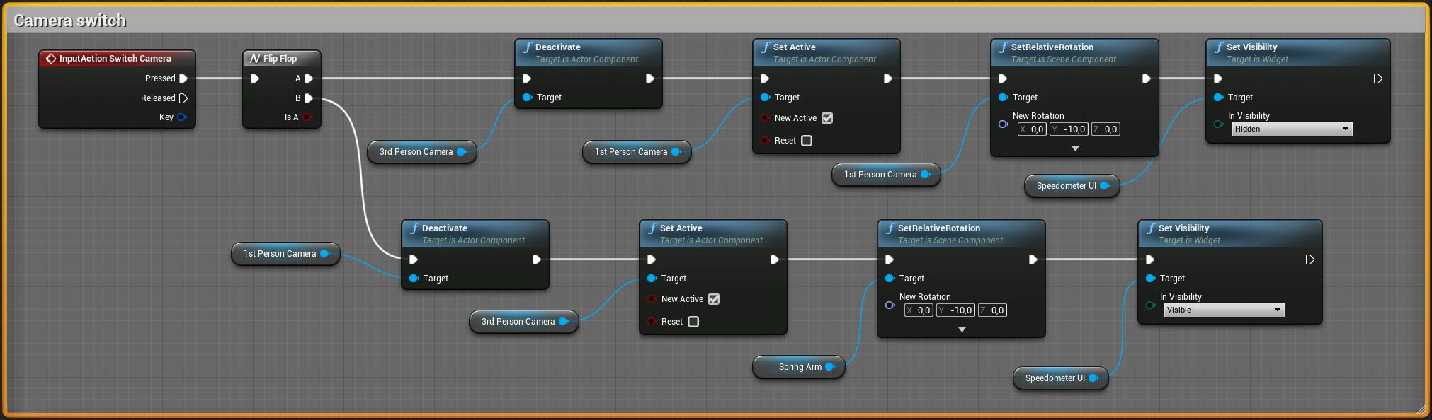
When we are switching to the first-person camera view, we are deactivating our third-person camera, then activating 1st person camera. Resetting its rotation and then hiding our Speedometer and Tachometer UI, because from the first-person view we can see them in the vehicle.
When we are switching back to the third-person camera, we are doing analogically. We deactivate 1st person camera, activate 3rd person camera, reset our 3rd person camera's rotation and make our UI visible again.
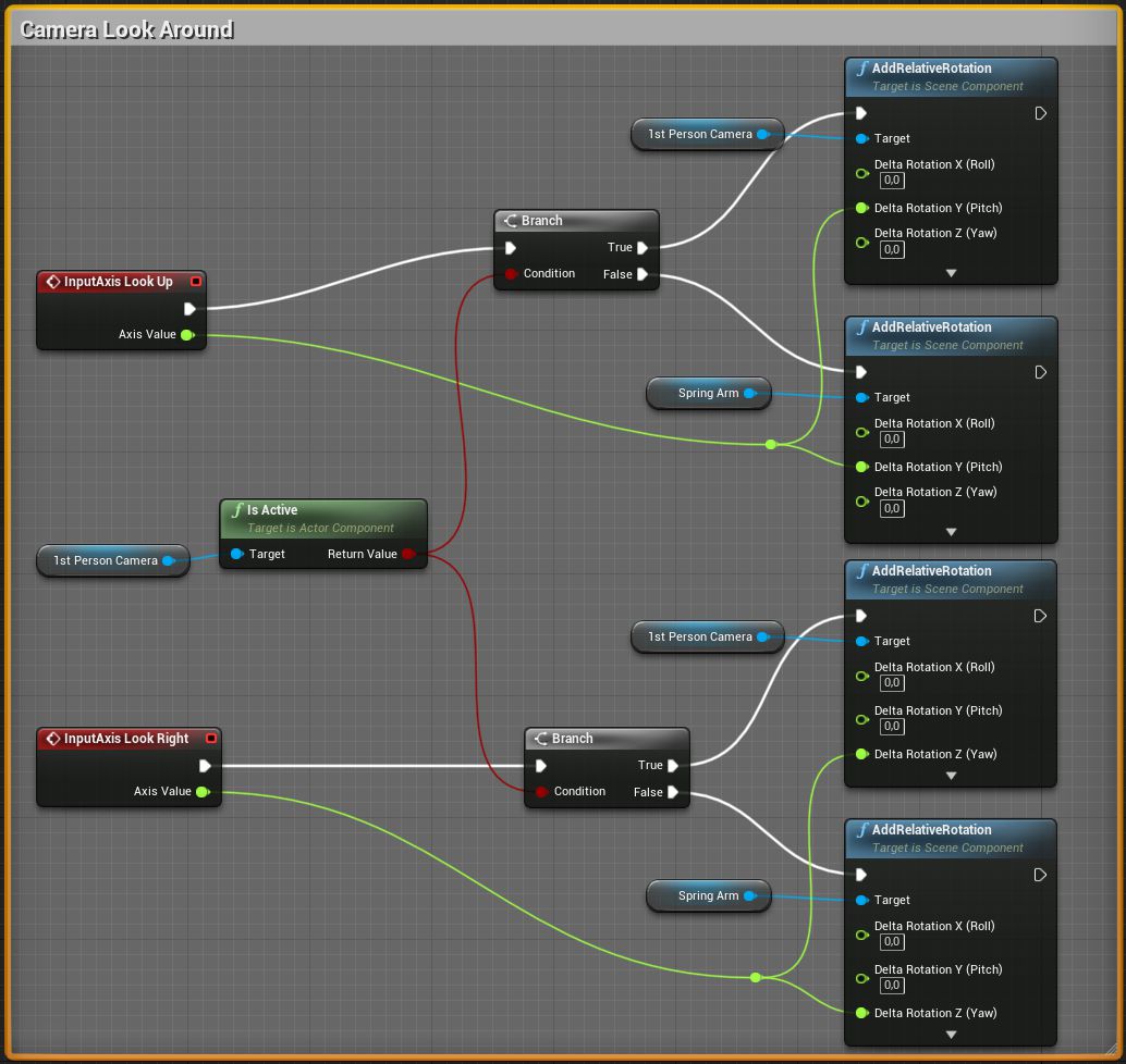
Right now we are resetting our first person camera's rotation, but we can't rotate it now. Let's add a possibility to look around with it when it's active.
In the Event Graph find the place where we are turning our third-person camera and change blueprints so they would look like in the image below.
Now we should have a vehicle that has a working speedometer and tachometer inside the vehicle and as the UI. Also we have another point of view for it and our in-vehicle speedometer and tachometer has backlight functionality.
Share on
Related Creations
Related Articles
How to get simple suspension animation for vehicle in UE4 with Blender 2.8
Tutorials Blender Unreal Engine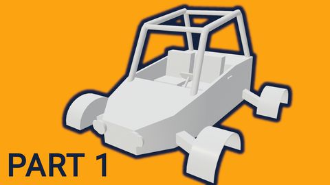
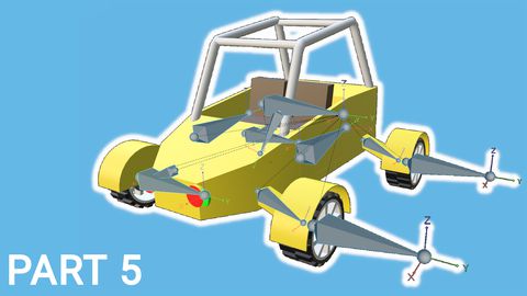
Rigging the vehicle model in Blender | [Part 5] Low poly vehicle for UE4
Tutorials Blender Unreal Engine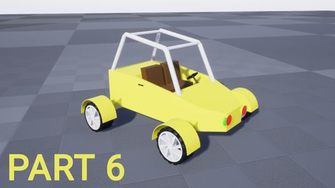
Setting up basic vehicle in Unreal Engine 4 | [Part 6] Low poly vehicle for UE4
Tutorials Unreal Engine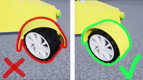
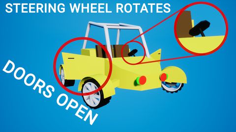
Making openable doors and animated steering wheel | [Part 8] Low poly vehicle for UE4
Tutorials Unreal Engine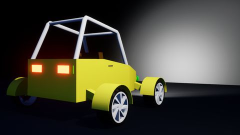
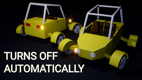
Adding turn signals with automatic turn off | [Part 11] Low poly vehicle for UE4
Tutorials Unreal Engine