Modeling low poly vehicle base in Blender | [Part 1] Low poly vehicle for UE4
by Arthur Ontuzhan
Posted 6 years, 5 months ago Last edit 2 years, 4 months ago
Categories: Tutorials Blender Tags: Vehicle Blender 2.8
Table of contents
- Introduction
- Modeling
- Setting up Blender project
- Vehicle carcass modeling
- Vehicle top tube frame modeling
- Door modeling
- Vehicle seat modeling
- Steering wheel modeling
- Speedometer modeling
- Tachometer modeling
- Tail lights modeling
- Rear turn lights modeling
- Front lights with turn lights modeling
- Wheel axles modeling
- Mudguards modeling
- Finalizing mesh
- Video
Introduction
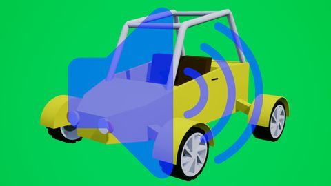
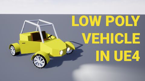
This is the first part of the tutorial series on how to create a low poly vehicle for Unreal Engine 4 using Blender and other free software. You can see the outcome of the tutorial series or get project files here.
In this tutorial we will model stylized low-poly buggy like vehicle without wheels in Blender. I will be using Blender 2.81.
You can find other parts here:
- [Part 2] Modeling low poly vehicle wheels.
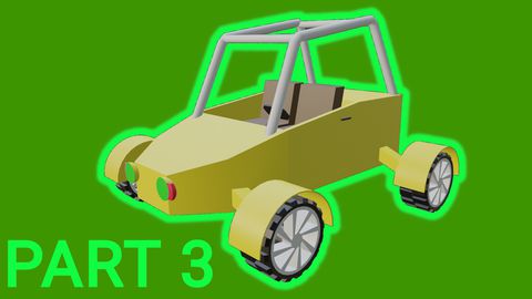
- [Part 3] Texturing the vehicle model.
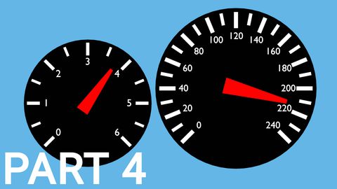
- [Part 4] Making speedometer and tachometer textures.
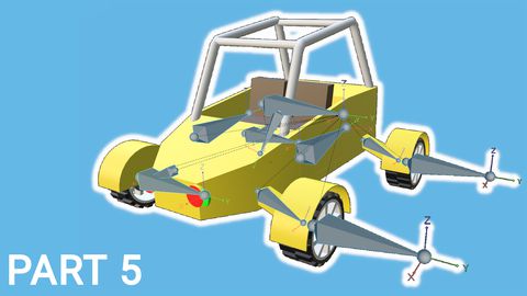
- [Part 5] Rigging vehicle the vehicle model.
- [Part 6] Setting up basic vehicle in Unreal Engine 4.
- [Part 7] Making mudguards and brake calipers move together with wheels.
- [Part 8] Making openable doors and animated steering wheel.
- [Part 9] Adding lights and brake lights.
- [Part 10] Adding speedometer and tachometer and first person camera.
- [Part 11] Adding turn signals with automatic turn off.
- [Part 12] Generating and setting up basic engine sounds.
Also, there's a video if you have difficulties to understand some parts.
Modeling
Setting up Blender project
We will start with an empty Blender project. Just open new project, and then select everything and delete.
- I prefer to do that by once pressing A key, then pressing X and then accepting deletion by hitting Enter or by mouse click.
- Or just do that your way.
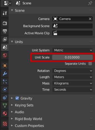
After this we need to change the scene Unit Scale to 0.01.
- We can find Unit Scale in the bottom right side of the Blender window. There we should select Scene tab, expand Units section and we will see Unit Scale value, which by default is 1. Also, make sure that the Unit System is set to Metric because UE4 uses the metric system.
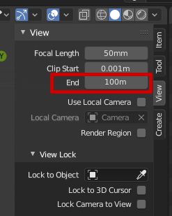
Now our project matches UE4 scaling, and now we will see that in 3D viewport we can't see objects in the further distance. To fix that we will increase Clipping distance.
- To increase 3D view Clip End distance, we need to press N key, which will open the properties menu on the top right corner of the 3D viewport. There under the View section, we will see the End value, which will be set to 10m. I usually set it to 100m, because I am too lazy to add more zeros. Most of the time 100m is enough for me to move a camera around. If this distance is not enough for you, you can always increase it, by default it's set to 1000m.
Vehicle carcass modeling
We will start by making the base of the vehicle base.
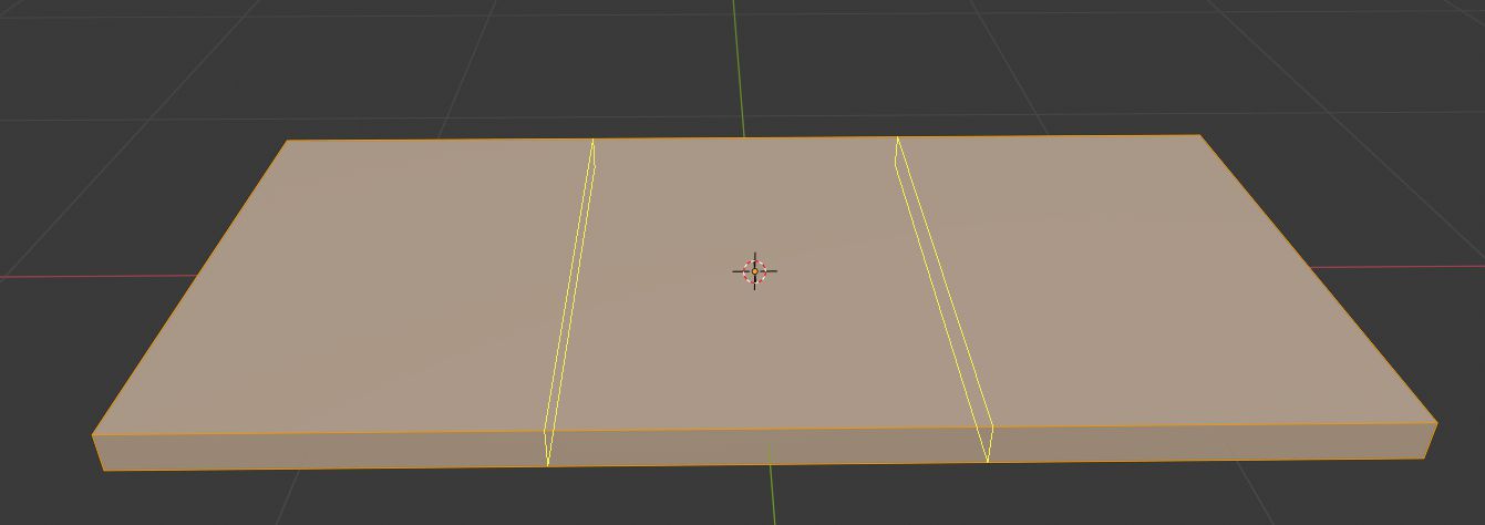
- Add Cube mesh - press Shift + A and then in Mesh sub-menu select Cube.
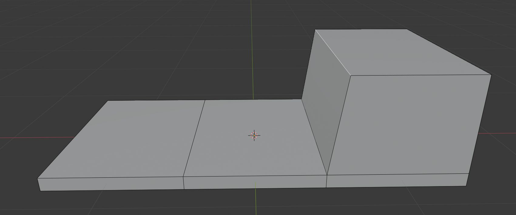
- Change its dimensions to X 2.9 m, Y 1.45 m, Z 0.1 m.
- Enter edit mode and add 2 loop cuts - press Tab, then mouse over the mesh and press Ctrl + R and scroll up mouse wheel once and accept action by left mouse click or pressing Enter.
Now we will make the backside of our base.
- Select top face which is located at a negative X-axis side, and extrude it upwards 0.7 m - Select face (press 3 to switch face selection) press E and type 0.7 and accept it by left mouse click or pressing Enter.
- Select extruded face's edge which is located towards mesh center and move it -0.1 m in X-axis - Select edge (press 2 to switch to edge selection) press G and type -0.1 and accept it by left mouse click or pressing Enter.
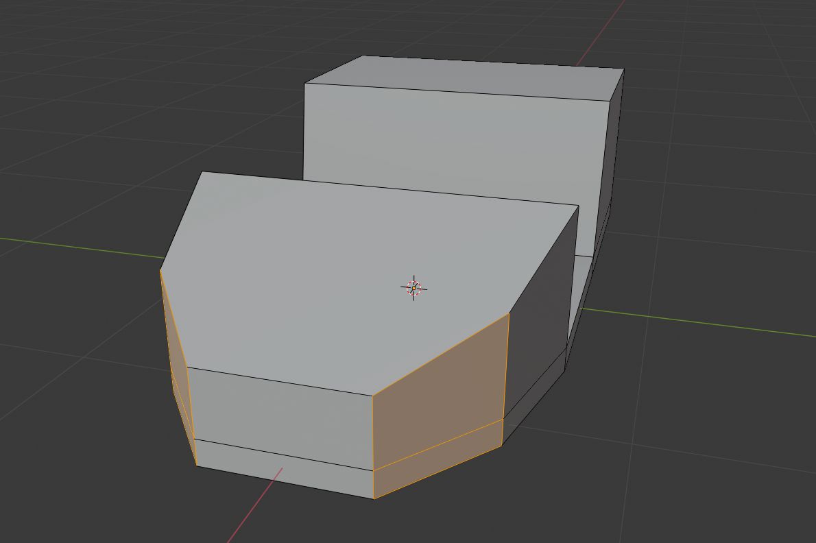
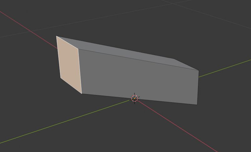
Now we will make a front side of base:
- Select a front face of the base and scale it by 0.7 on Y-axis - Select face press S and then Y and type 0.7 and accept it by left mouse click or pressing Enter.
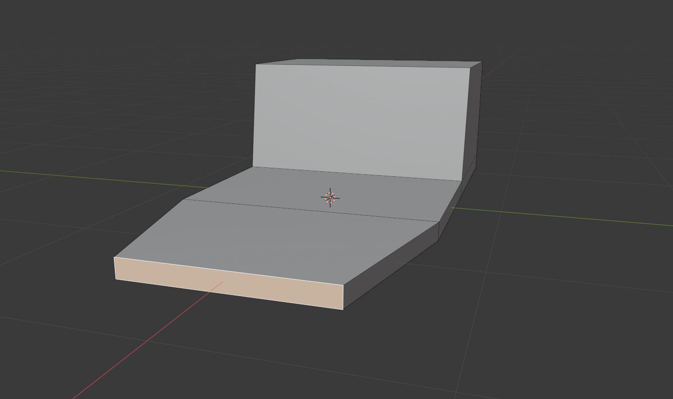
- Select a front top face and extrude it upwards 0.55 m - Select face press E and type 0.55 and accept it by left mouse click or pressing Enter.
- Lower front edge by 0.3 m - Select edge press G and then Z and type -0.3 and accept it by left mouse click or pressing Enter.
- Select front side edges and bevel them by 0.3 - Select front side edges and press B and type 0.3 and accept it by left mouse click or pressing Enter.
Vehicle top tube frame modeling
Now we will add the top part of our vehicle which is made out of tubes.
We will make our tubes by using paths. Let's start by making a side path which we can duplicate for another side later.
- Add Path - press Shift + A and then in Curve sub-menu select Path.
- Move it up by 2 m so we could see it better - press G and type 2 and then accept it by left mouse click or pressing Enter.
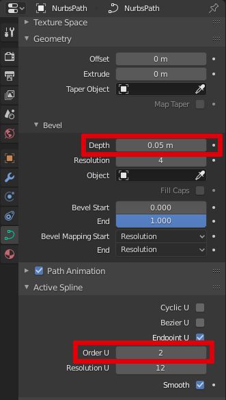
- In Object Data Properties tab in Geometry section set Bevel Depth to 0.05 m. This will make the path to look like a tube.
- In Object Data Properties tab in Active Spline section set Order U to 2. This will make our tube corners sharper.
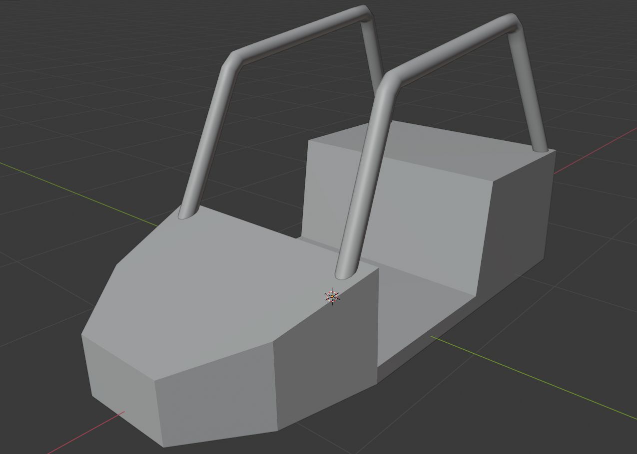
Now our path looks like a tube and we can place it.
- Enter edit mode - press Tab
- Delete one end vertice - Select vertice and press X or Delete and in menu select Vertices. By default we get 5 vertices and we need only 4.
- Now we will place each vertice by changing its Global coordinates in the Item Properties section - In Item Properties (N to open properties menu) set values press Global button to set values to global.
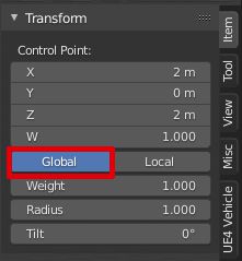
- Set vertices to these coordinates. You can also see them in the image below.
- X 0.6 m, Y 0.6 m, Z 0.5 m
- X 0.2 m, Y 0.55 m, Z 1.4 m
- X -1 m, Y 0.55 m, Z 1.6 m
- X -1.4 m, Y 0.65 m, Z 0.7 m

- Now to get other side tube we can set Transform Pivot Point to 3D Cursor (it will only work if 3D cursor is in default position, to reset 3D cursor position press Shif + C) just copy this tube and scale it by -1 on Y-axis
- If you in edit mode select all tube's vertices by pressing A, if you in object mode, just select tube by left mouse click.
- At the top part of 3D viewport change Transform Pivot Point to 3D Cursor.
- Reset 3D cursor if you need by pressing Shift + C.
- Duplicate tube by pressing Shift + D then press S and press Y and type -1 and then accept operation by left mouse click or pressing Enter.
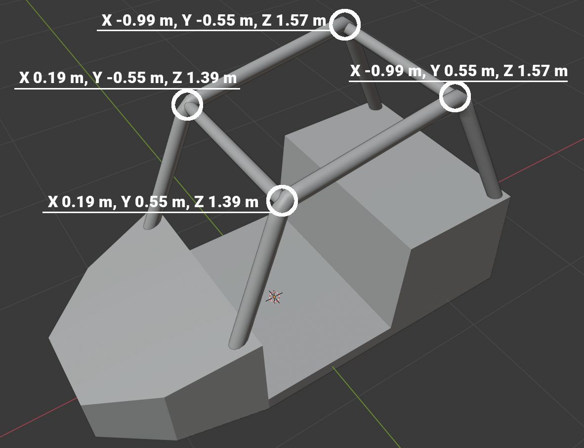
Now we will add 2 more tubes which will connect side tubes, but these tubes will be a little smaller than side tubes.
- Add Path - press Shift + A and then in Curve sub-menu select Path.
- Move it up by 2 m so we could see it better - press G and type 2 and then accept it by left mouse click or pressing Enter.
- In Object Data Properties tab in Geometry section set Bevel Depth to 0.04 m. This will make the path to look like a tube.
- Enter edit mode - press Tab.
- Delete unneeded vertices so at the end we would get 2 - Select vertices and press X or Delete and in menu select Vertices.
- Set vertices global coordinates to X -0.99 m, Y 0.55 m, Z 1.57 m and X -0.99 m, Y -0.55 m, Z 1.57 m
- Duplicate tube - If you in edit mode select all tube's vertices by pressing A, if you in object mode, just select tube by left mouse click and then press Shift + D.
- Set new tube's vertices global coordinates to X 0.19 m, Y 0.55 m, Z 1.39 m and X 0.19 m, Y -0.55 m, Z 1.39 m
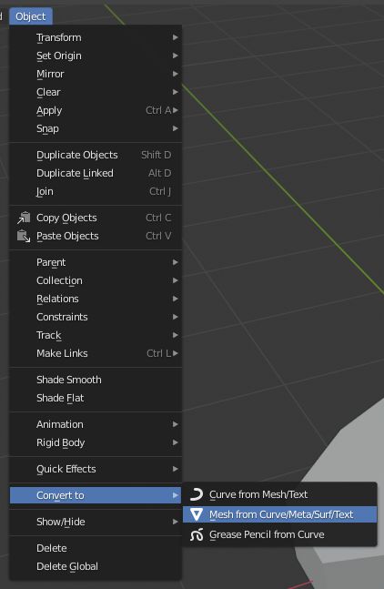
Now we will join our tubes to base mesh. But before we do that, at first we need to convert our tubes from curve objects to mesh objects.
- In the object mode select all tubes while holding down Shift.
- In Object menu go to Convert To and select Mesh from Curve/Meta/Surf/Text.
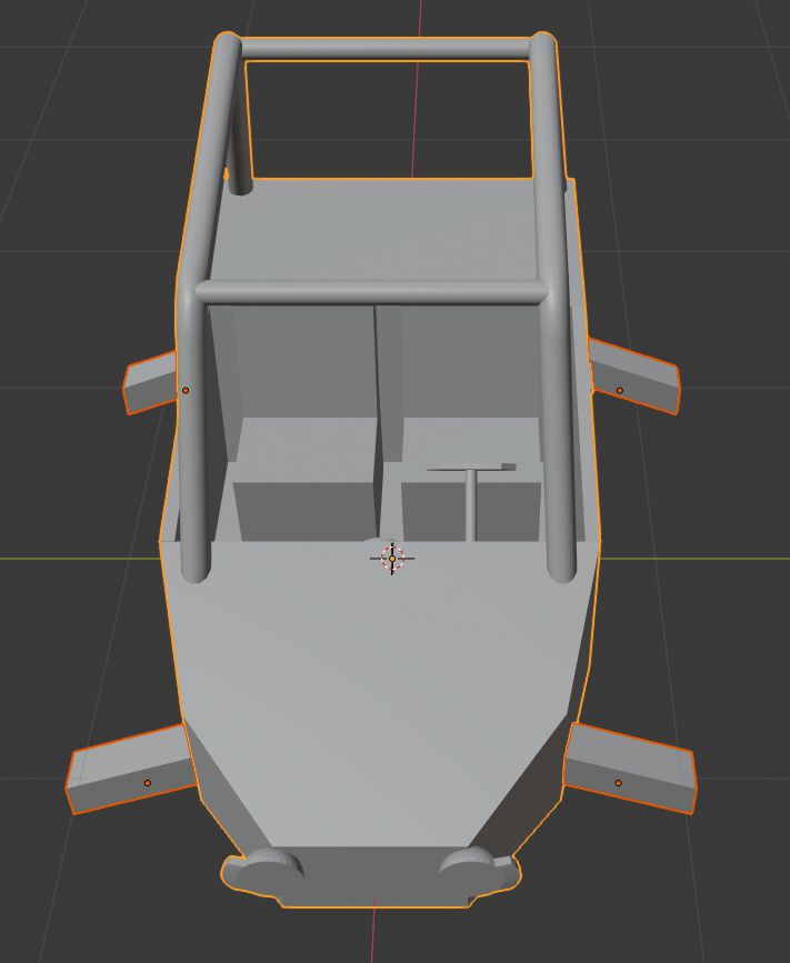
Now we can join our tube meshes to the base mesh.
- In the object mode select all tubes and the base mesh by holding down Shift, make sure that you select base mesh last. You can see how selection should look in the image below.
- Press Ctrl + J to join meshes together.

Door modeling
Now we will model doors. We will start by adding a cube and shaping it to the door shape.
- Add Cube mesh - press Shift + A and then in Mesh sub-menu select Cube.
- Change its Y dimensions to Y 0.05 m.
- Enter edit mode and enable X-Ray - press Tab and then press Alt+Z. You can also use wireframe mode - Z then 4.
- Enable Snapping Shift+Tab and in snapping settings set Snap to Edge. You can find snapping settings at the top mid part of the viewport
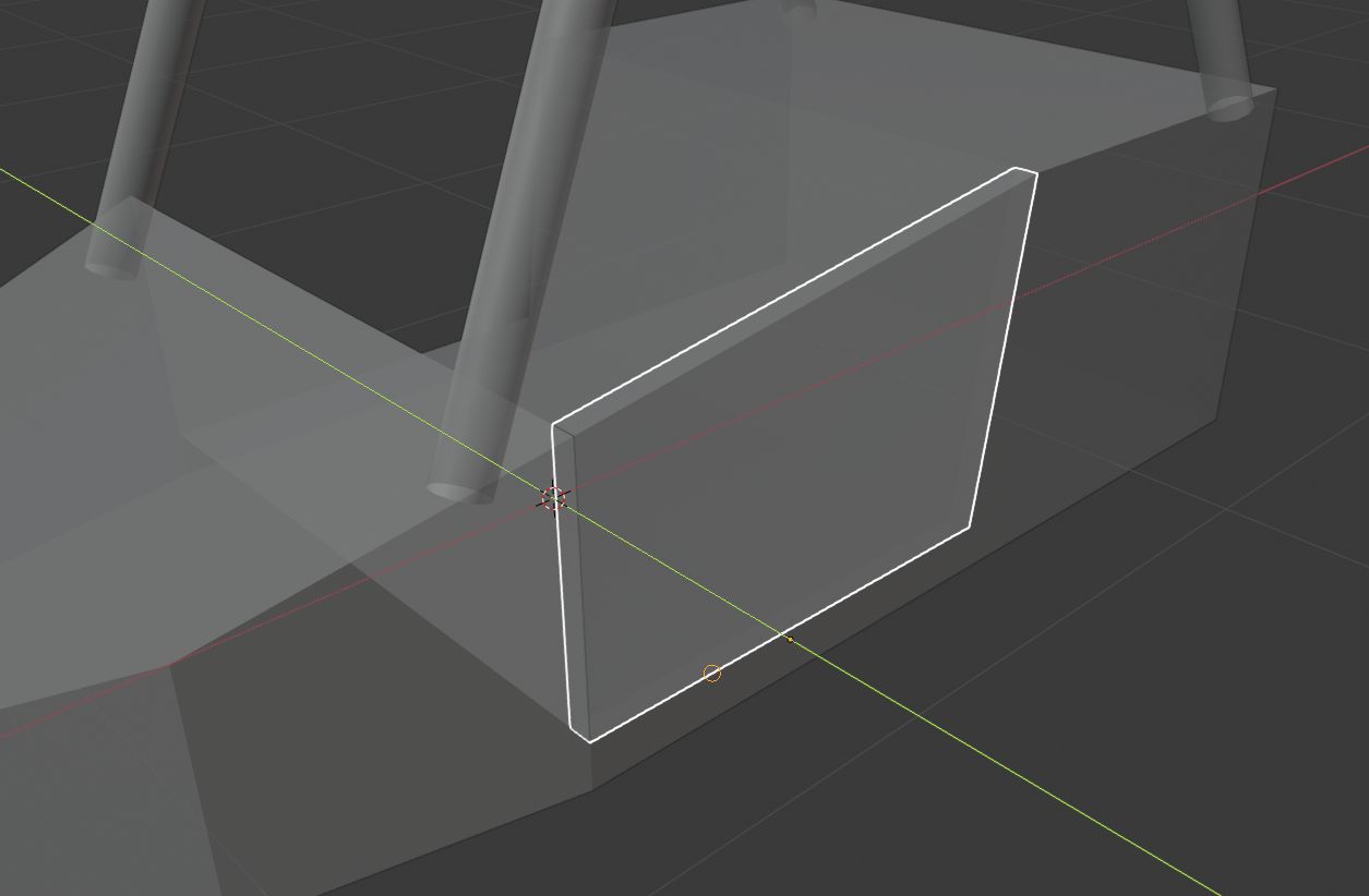
- Now select Cube outer short edges and move them by X and Z axis into the vehicle by snapping them to edges in vehicle base (see in the image below)
- Select edge.
- Press G and then Shift+Y.
- Move edge until it snaps to the desired vehicle base edge and accept a move by left mouse click or pressing Enter.
- Repeat previous steps until the cube is shaped into a vehicle base.
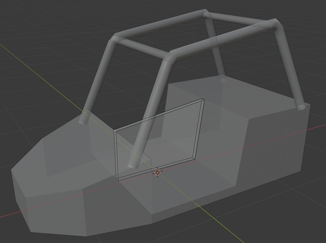
Now we can go to object mode and snap it to the base side, so it would be in the correct door place.
- Switch to object mode - press Tab.
- Move door to vehicle side - press G and then press Y and slide the door till it snaps to vehicle side edge and accept a move by left mouse click or pressing Enter. Example in the image below.
Now we will add a door handle to our door and make a second door.
- Add Cube mesh - press Shift + A and then in Mesh sub-menu select Cube.
- Change its dimensions to X 0.15 m, Y 0.02 m, Z 0.02 m.
- Set its location to X -0.35 m, Y 0.735 m, Z 0.6 m. Or you can use snap to face transform and place it on the door where you want.
- Select handle and doors while holding Shift.
- Join them together by pressing Ctrl + J.
- Make sure that the transform pivot point is set to the 3D cursor and the 3D cursor is in its default position (Shift + C to reset 3D cursor).
- Create another door by copying this one. Press Shift + D then press S and press Y and type -1 and then accept operation by left mouse click or pressing Enter.
- Select both doors and the base mesh by holding down Shift, make sure that you select base mesh last. You can see how selection should look in the image below.
- Press Ctrl + J to join meshes together.

Vehicle seat modeling
Now we will model seats. To make their modeling easier, we will hide our vehicle base mesh.
- Select vehicle base mesh and hide by pressing H (press Alt+H to unhide hidden objects).
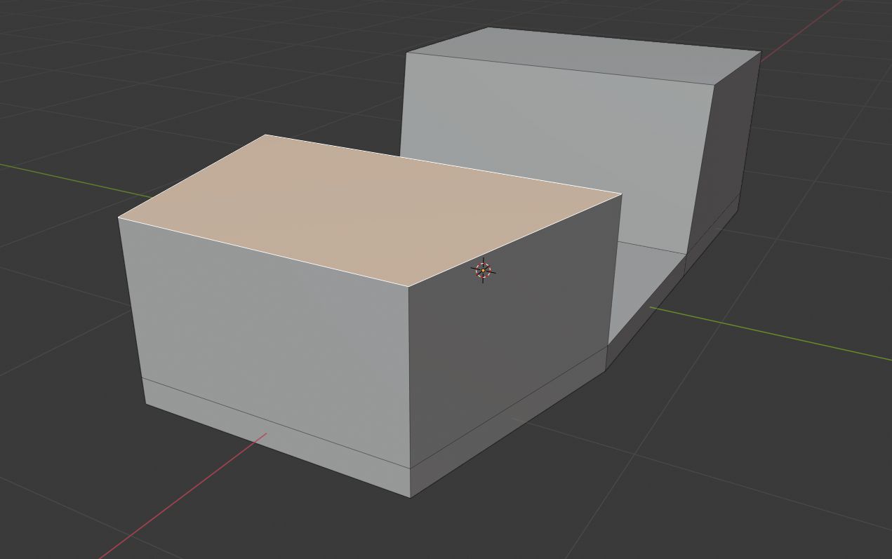
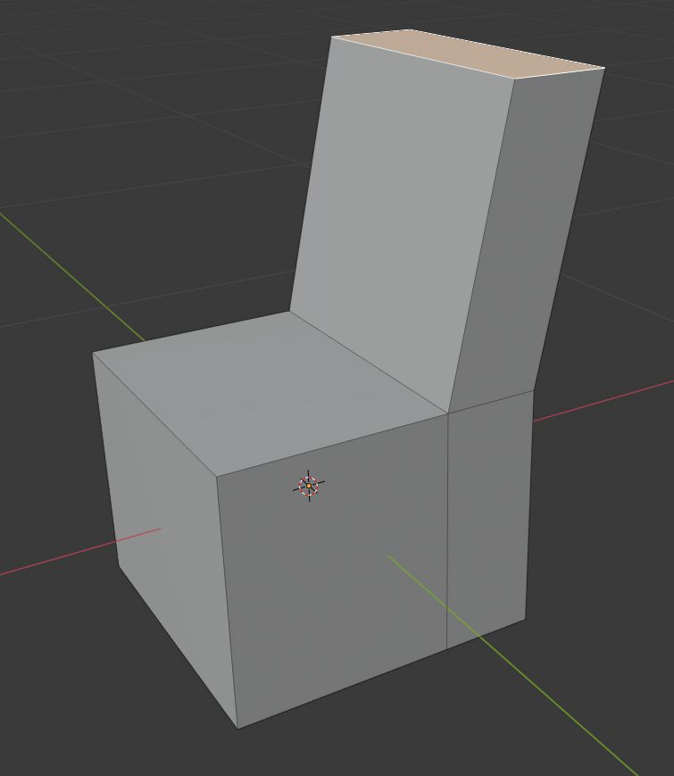
- Add Cube mesh - press Shift + A and then in Mesh sub-menu select Cube.
- Change its dimensions to X 0.5 m, Y 0.5 m, Z 0.4 m.
- Enter edit mode and add loop cut - press Tab, then mouse over the mesh and press Ctrl + R and accept action by left mouse click or pressing Enter.
- Move loop cut -0.1 m in X-axis - while loop cut is selected press G and type -0.1 and accept action by left mouse click or pressing Enter.
- Select a smallest top face and extrude it upwards 0.45 m - Select face press E and type 0.45 and accept it by left mouse click or pressing Enter.
- While top face after the previous operation is still selected move it by -0.1 m in X-axis - while the face is selected press G then X and type -0.1 and accept action by left mouse click or pressing Enter.
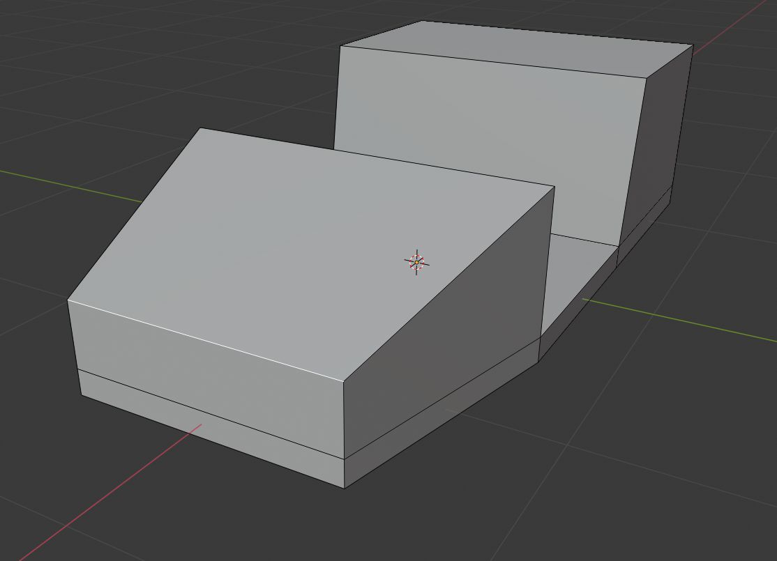
Now we can unhide our vehicle base mesh and place our seats into it.
- Exit edit mode - press Tab.
- Unhide base mesh - press Alt+H.
- Select seat and set its location to X -0.2 m, Y 0.3 m, Z 0.25 m.
- Make sure that the transform pivot point is set to the 3D cursor and the 3D cursor is in its default position (Shift + C to reset 3D cursor).
- Create another seat by copying this one - press Shift + D then press S and press Y and type -1 and then accept operation by left mouse click or pressing Enter.
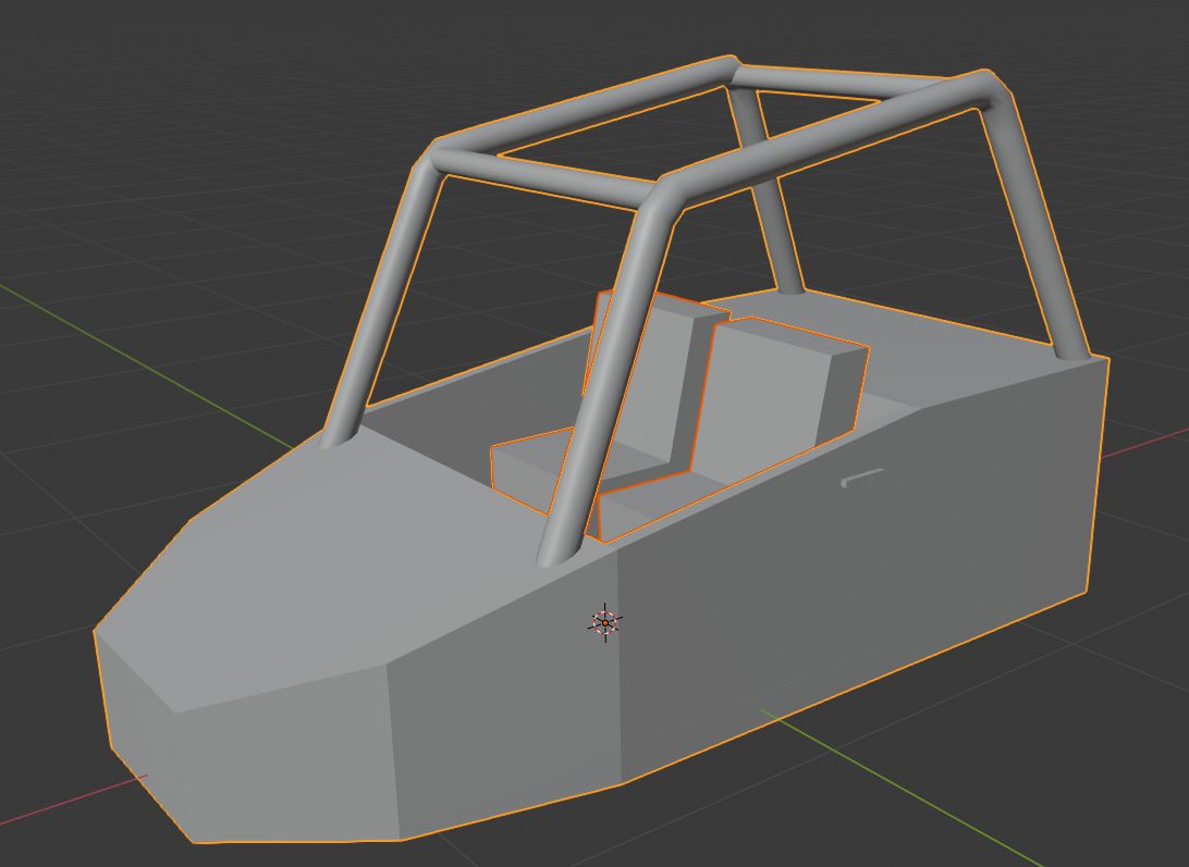
- Select both seats and the base mesh by holding down Shift, make sure that you select base mesh last. You can see how selection should look in the image below.
- Press Ctrl + J to join meshes together.
Steering wheel modeling
Now we will model a steering wheel. To make modeling easier, we will hide our vehicle base mesh.
- Select vehicle base mesh and hide by pressing H (press Alt+H to unhide hidden objects).
- Add Cylinder mesh - press Shift + A and then in Mesh sub-menu select Cylinder.
- In the Add Cylinder widget set its Radius to 0.02 m and Depth to 0.5 m.
- Add Cube mesh - press Shift + A and then in Mesh sub-menu select Cube.
- Change cube's dimensions to X 0.2 m, Y 0.3 m, Z 0.02 m.
- Select the cube and apply scale to it - press Ctrl+A and select Scale.
- While cube selected enter in edit mode - press Tab.
- Select cube short edges and bevel by 0.05 - Select edges and press Ctrl+B and type 0.05 and accept action by left mouse click or pressing Enter.

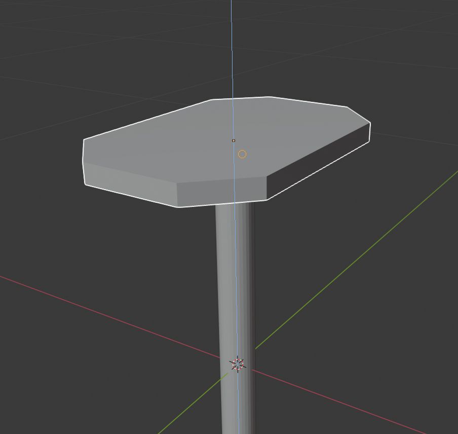
Now we have both parts for our steering wheel. Let's put them together and put the steering wheel in its place.
- Exit edit mode - press Tab.
- Select steering wheel part which we made from the cube and move it upwards on Z-axis until it's over cylinder part - Select part, press G and then Z and move it over the cylinder and accept action by left mouse click or pressing Enter.
- Enable Snapping Shift+Tab and in snapping settings set Snap to Face.
- Snap part on top of the cylinder - press G and then press Z and slide the part till it snaps on top of the cylinder and accept a move by left mouse click or pressing Enter. Example in the image below.
- Select both parts by holding down Shift, make sure that you select cylinder mesh last.
- Press Ctrl + J to join meshes together.
We have our steering wheel mesh done, now we can place it in its place.
- Unhide base mesh - press Alt+H.
- Select the steering wheel and set its location to X 0.4 m, Y 0.3 m, Z 0.5 m.
- Set its Y rotation to -45 degrees.
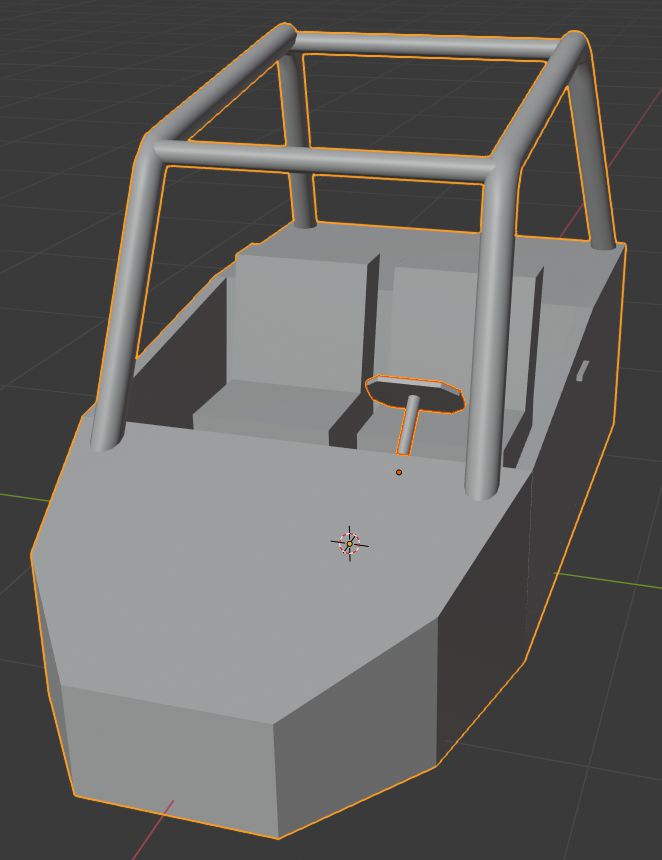
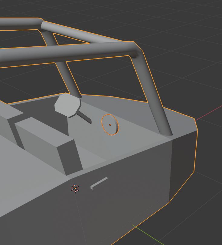
- Select steering wheel and the base mesh by holding down Shift, make sure that you select base mesh last. You can see how selection should look in the image below.
- Press Ctrl + J to join meshes together.
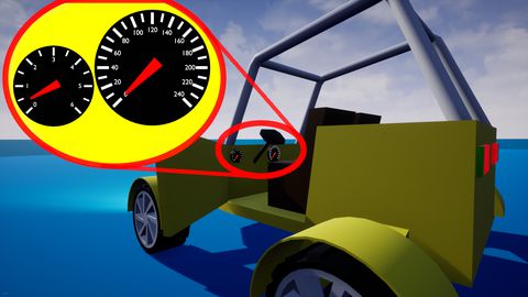
Speedometer modeling
Just read the title of this part.
- Add Cylinder mesh - press Shift + A and then in Mesh sub-menu select Cylinder.
- In the Add Cylinder widget set its Radius to 0.1 m and Depth to 0.03 m.
- Rotate it by 90 degrees on Y-axis - Press R then press Y and type 90 and accept a move by left mouse click or pressing Enter.
- Set its location to X 0.47 m, Y 0 m, Z 0.49 m.
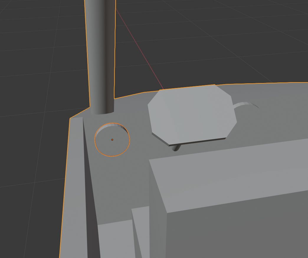
- Select speedometer and the base mesh by holding down Shift, make sure that you select base mesh last. You can see how selection should look in the image below.
- Press Ctrl + J to join meshes together.
Tachometer modeling
Same as speedometer just with slightly different numbers.
- Add Cylinder mesh - press Shift + A and then in Mesh sub-menu select Cylinder.
- In the Add Cylinder widget set its Radius to 0.07 m and Depth to 0.03 m.
- Rotate it by 90 degrees on Y-axis - Press R then press Y and type 90 and accept a move by left mouse click or pressing Enter.
- Set its location to X 0.47 m, Y 0.57 m, Z 0.49 m.
- Select speedometer and the base mesh by holding down Shift, make sure that you select base mesh last. You can see how selection should look in the image below.
- Press Ctrl + J to join meshes together.
Tail lights modeling
- Add Cube mesh - press Shift + A and then in Mesh sub-menu select Cube.
- Change cube's dimensions to X 0.02 m, Y 0.3 m, Z 0.15 m.
- Set its location to X -1.46 m, Y 0.4 m, Z 0.55 m.
- Make sure that the transform pivot point is set to the 3D cursor and the 3D cursor is in its default position (Shift + C to reset 3D cursor).
- Create another light by copying this one - press Shift + D then press S and press Y and type -1 and then accept operation by left mouse click or pressing Enter.
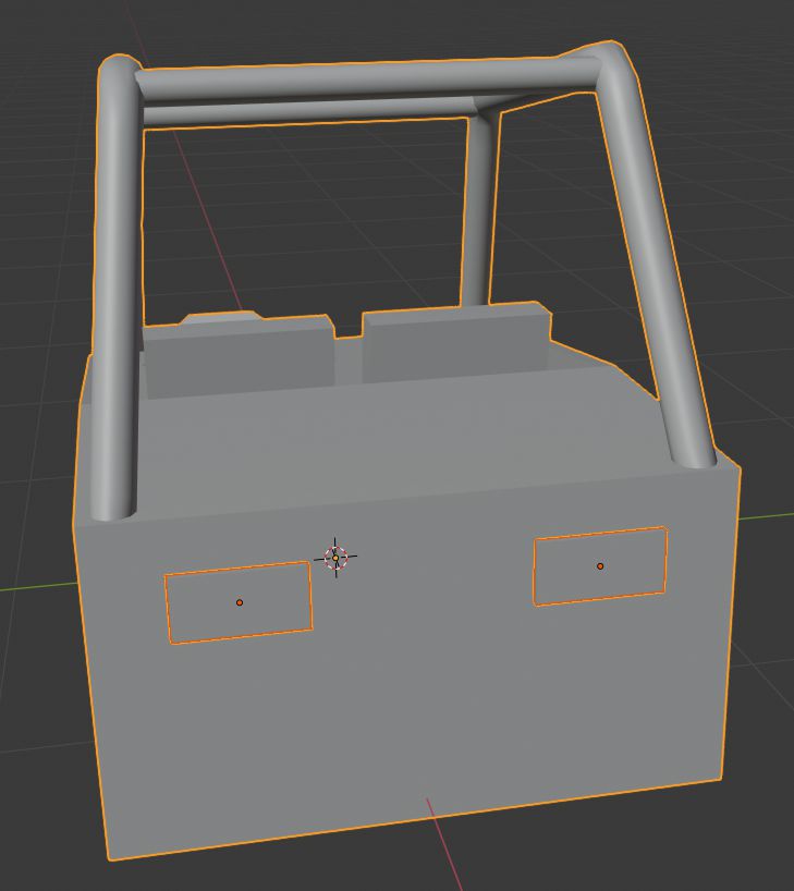
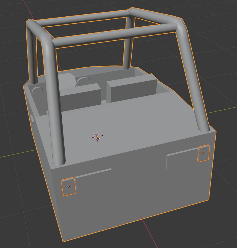
- Select lights and the base mesh by holding down Shift, make sure that you select base mesh last. You can see how selection should look in the image below.
- Press Ctrl + J to join meshes together.
Rear turn lights modeling
Same as tail lights just with slightly different numbers.
- Add Cube mesh - press Shift + A and then in Mesh sub-menu select Cube.
- Change cube's dimensions to X 0.02 m, Y 0.1 m, Z 0.15 m.
- Set its location to X -1.46 m, Y 0.61 m, Z 0.55 m.
- Make sure that the transform pivot point is set to the 3D cursor and the 3D cursor is in its default position (Shift + C to reset 3D cursor).
- Create another light by copying this one - press Shift + D then press S and press Y and type -1 and then accept operation by left mouse click or pressing Enter.
- Select lights and the base mesh by holding down Shift, make sure that you select base mesh last. You can see how selection should look in the image below.
- Press Ctrl + J to join meshes together.
Front lights with turn lights modeling
- Select vehicle base mesh and hide by pressing H (press Alt+H to unhide hidden objects).
- Add Sphere mesh - press Shift + A and then in Mesh sub-menu select UV Sphere.
- In the Add UV Sphere widget set its Radius to 0.1 m.
- Remove half of the sphere:
- Enter edit mode - Tab.
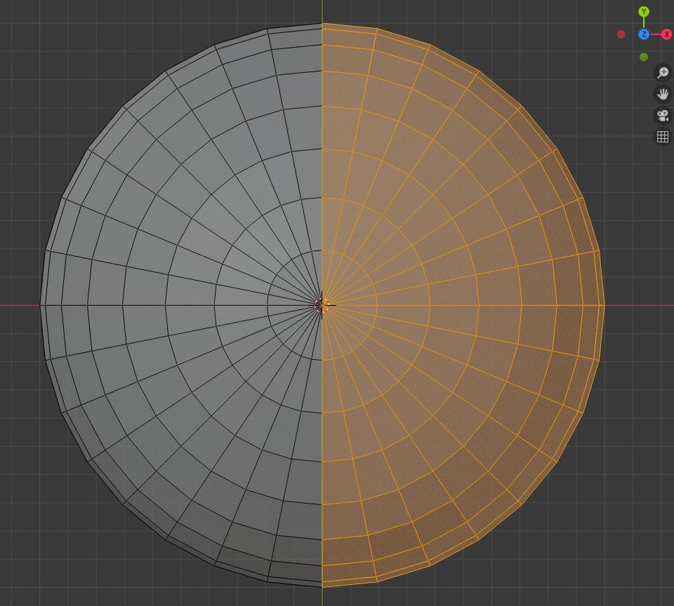
- Go to Top Orthographic view - Num 7.
- Enable X-ray - press Alt+Z.
- With box select tool (B) select sphere half which is faced towards positive X-Axis. See image below
- Press X and in menu select Faces.
- Disable X-ray - press Alt+Z.
- Select sphere opening edges by holding Alt and clicking on one of the opening edges.
- Fill the selection with a face - press F.

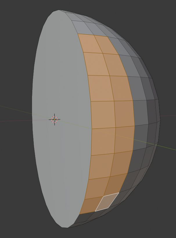
Now our base front light shape is done. Now we will add turn signals to them.
- Select 2x8 faces on the positive Y-axis side of the half sphere. Look at the image below.
- Extrude faces by 0.05 m - press E and type 0.05 and then accept operation by left mouse click or pressing Enter.
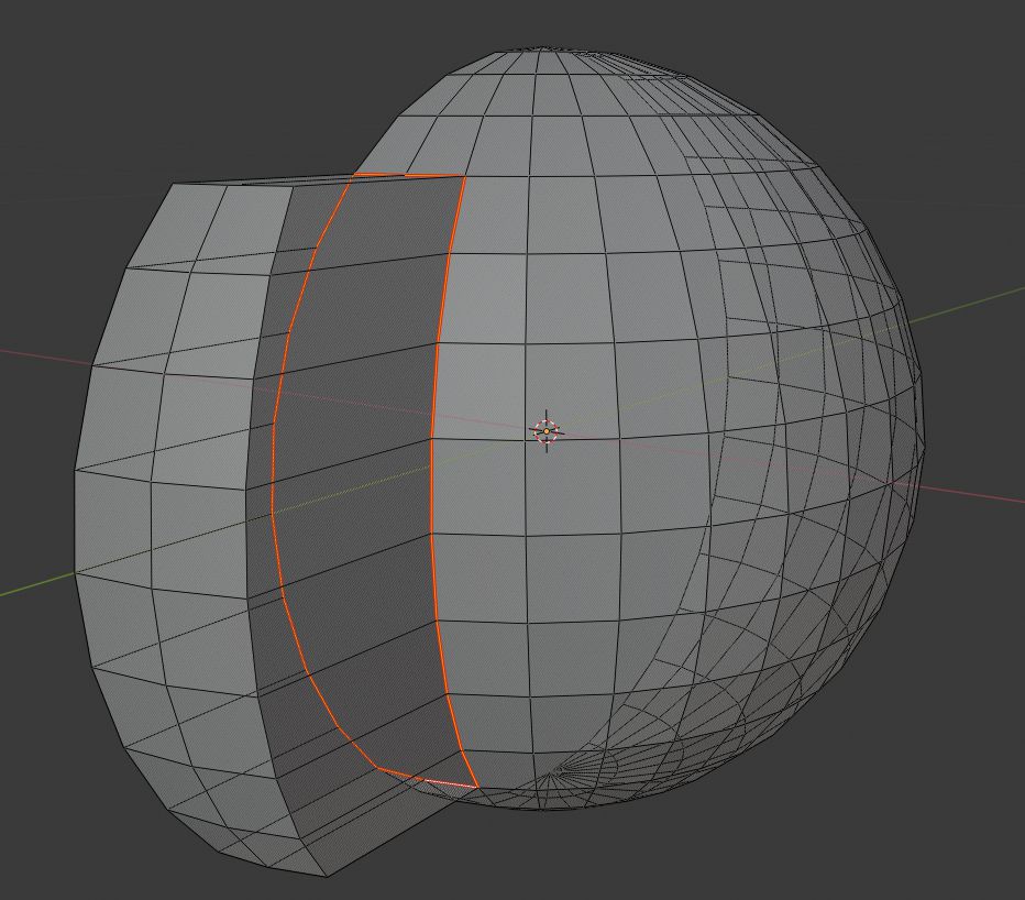
To have fewer things to do when we will texture our model, we will mark seam for this mesh around the extruded part.
- Select edges like shown in the image below. I have enabled X-ray in the image below, so I could show which edges to select.
- Press Ctrl+E and select Mark Seam.
- Exit edit mode - Tab.
- Unhide base mesh - press Alt+H.
- Select the front light mesh and set its location to X 1.5 m, Y 0.3 m, Z 0.2 m.
- Make sure that the transform pivot point is set to the 3D cursor and the 3D cursor is in its default position (Shift + C to reset 3D cursor).
- Create another front light by copying this one - press Shift + D then press S and press Y and type -1 and then accept operation by left mouse click or pressing Enter.
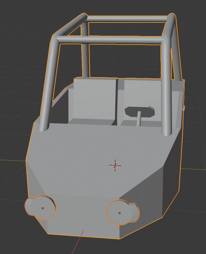
- Select front lights and the base mesh by holding down Shift, make sure that you select base mesh last. You can see how selection should look in the image below.
- Press Ctrl + J to join meshes together.
Wheel axles modeling
Things that will attach our wheels to the vehicle base.
- Select vehicle base mesh and hide by pressing H (press Alt+H to unhide hidden objects).
- Add Cube mesh - press Shift + A and then in Mesh sub-menu select Cube.
- Change cube's dimensions to X 0.15 m, Y 0.5 m, Z 0.15 m.
- Go in edit mode - Tab.
- Select face which faces towards negative Y-axis and move it up by 0.2 m - Select face, press G then press Z and type 0.2 and then accept operation by left mouse click or pressing Enter.
- Exit edit mode - Tab.
- Unhide base mesh - press Alt+H.
- Select axle mesh and set its location to X -1.1 m, Y 0.95 m, Z -0.1 m.
- Duplicate axle (Shift+D) and set a new axle location to X 0.95 m, Y 0.8 m, Z -0.1 m.
- Make sure that the transform pivot point is set to the 3D cursor and the 3D cursor is in its default position (Shift + C to reset 3D cursor).
- Select both axles and duplicate them Shift + D then press S and press Y and type -1 and then accept operation by left mouse click or pressing Enter.
- Select axles and the base mesh by holding down Shift, make sure that you select base mesh last. You can see how selection should look in the image below.
- Press Ctrl + J to join meshes together.
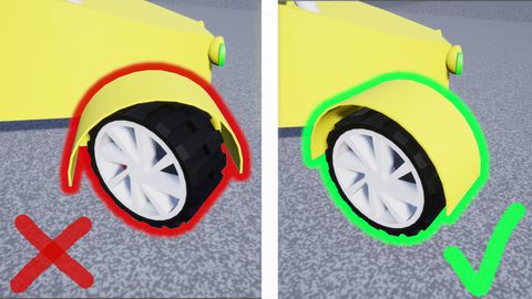
Mudguards modeling
- Select vehicle base mesh and hide by pressing H (press Alt+H to unhide hidden objects).
- Add Cylinder mesh - press Shift + A and then in Mesh sub-menu select Cylinder.
- In the Add Cylinder widget set its Radius to 0.4 m and Depth to 0.35 m.
- Rotate mesh by 90 degrees in X-axis - press R and type 90 and then accept operation by left mouse click or pressing Enter.
- Go in edit mode - Tab.
- Select both circle faces and bottom half of cylinder faces and then press X and select Faces.
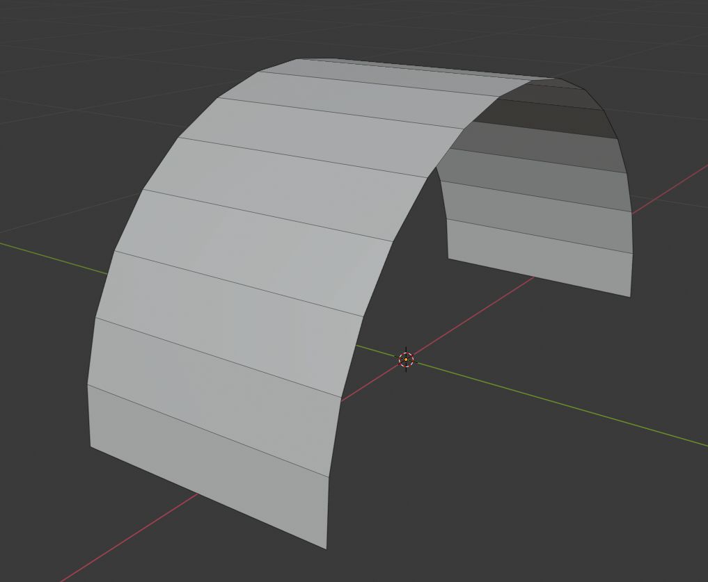
- Select side edges (hold Alt and click on one) which are at the negative Y-axis side and make a new face by pressing F.
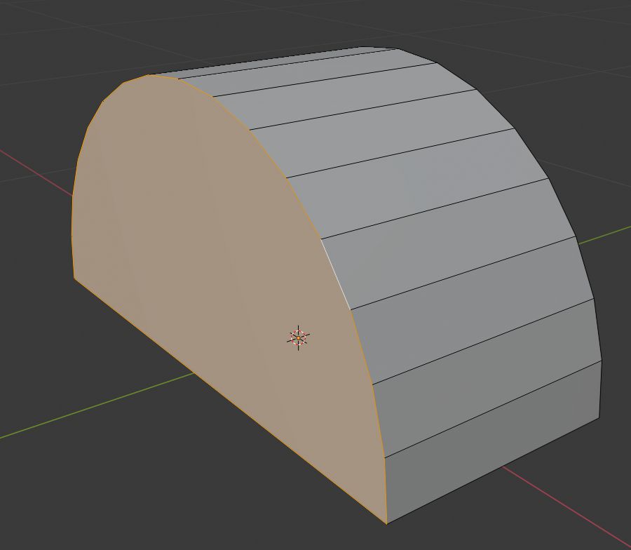
- Exit edit mode - Tab.
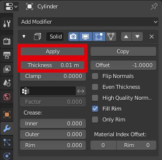
- Add Solidify modifier to the mesh, set Thickness to 0.01 m.
- Press the Apply button to apply the modifier.
- Unhide base mesh - press Alt+H.
- Select mudguard mesh and set its location to X -1.1 m, Y 1.3 m, Z -0.1 m.
- Duplicate mudguard (Shift+D) and set a new mudguard location to X 0.95 m, Y 1.15 m, Z -0.1 m.
- Make sure that the transform pivot point is set to the 3D cursor and the 3D cursor is in its default position (Shift + C to reset 3D cursor).
- Select both mudguards and duplicate them Shift + D then press S and press Y and type -1 and then accept operation by left mouse click or pressing Enter.
- Select mudguards and the base mesh by holding down Shift, make sure that you select base mesh last. You can see how selection should look in the image below.
- Press Ctrl + J to join meshes together.
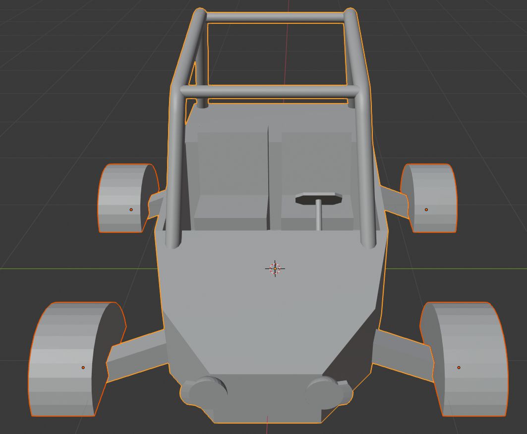
As we can see, our mesh now has weird artifacts from smoothing. We will fix that by applying auto smooth to our mesh.
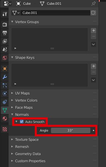
- Select mesh and apply scale to it - press Ctrl+A and select Scale. This will make auto smooth work correctly.
- In Object Data Properties tab in Normals section check Auto Smooth.
- We still might see some artifacts in our case so we will increase Angle to 33°.
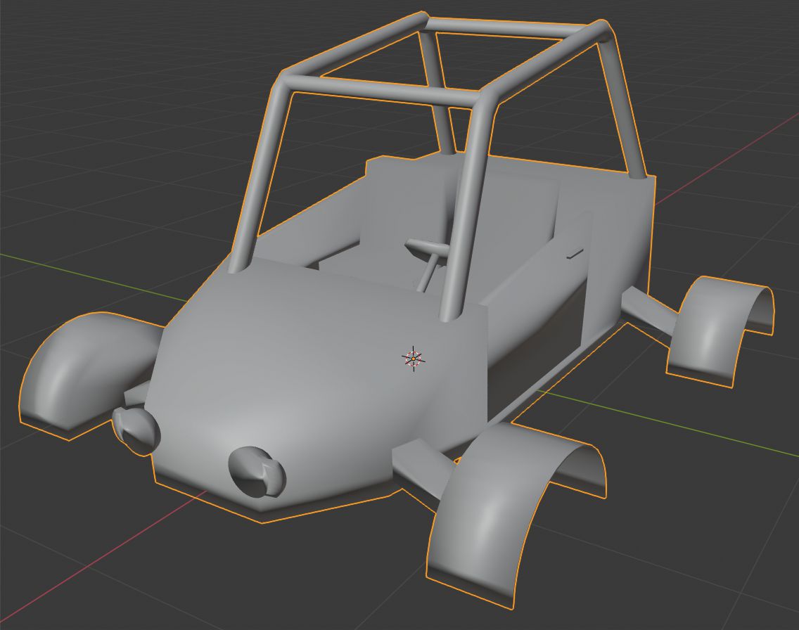
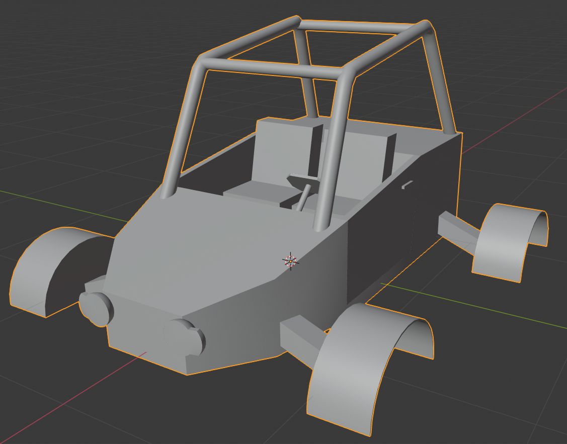
Now we should get mesh like in the image below.
Mesh might look fine now, but there's one more thing which we need to do. We need to make sure, that mesh normals has the right orientation. At first, we want to see normal orientation.
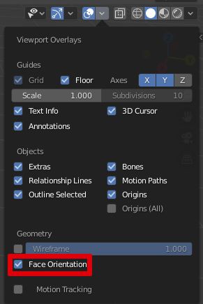
- At the top right side of the viewport open Overlays menu and check Face Orientation.
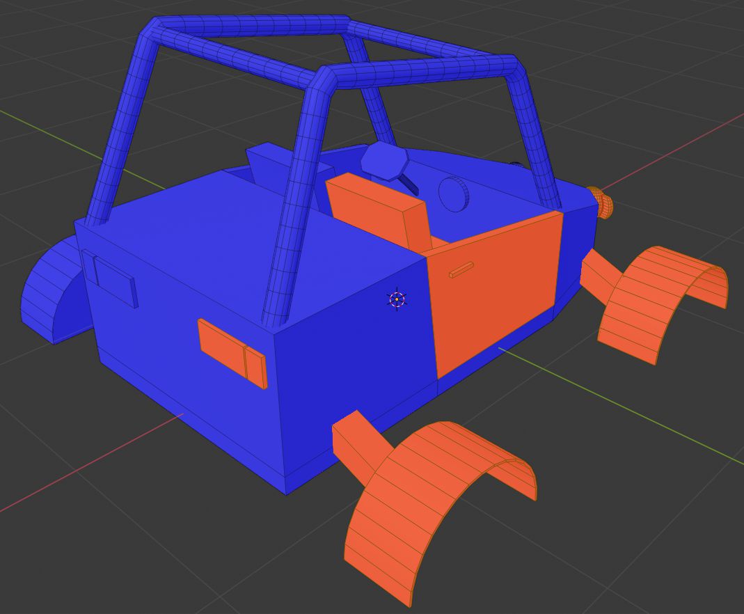
Now you will see mesh colored in blue and red colors. Red color means, that normals at that place are inverted. We need to make the whole mesh in blue color.
- Go into edit mode - Tab.
- Mouse over red mesh part and press L to select the red mesh part.
- After you selected all red parts press Alt+N and select Flip. See in the image below how selection should look like.
Now we have our vehicle base done. In the next part, we will create wheels for our vehicle.
Share on
Related Creations
Related Articles
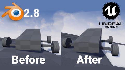
How to get simple suspension animation for vehicle in UE4 with Blender 2.8
Tutorials Blender Unreal Engine
Rigging the vehicle model in Blender | [Part 5] Low poly vehicle for UE4
Tutorials Blender Unreal Engine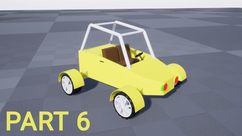
Setting up basic vehicle in Unreal Engine 4 | [Part 6] Low poly vehicle for UE4
Tutorials Unreal Engine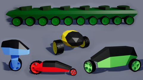
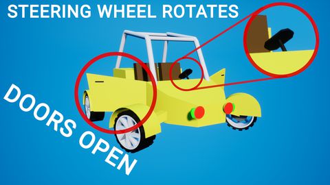
Making openable doors and animated steering wheel | [Part 8] Low poly vehicle for UE4
Tutorials Unreal Engine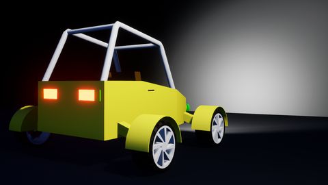
Adding speedometer and tachometer and 1st person camera | [Part 10] Low poly vehicle for UE4
Tutorials Unreal Engine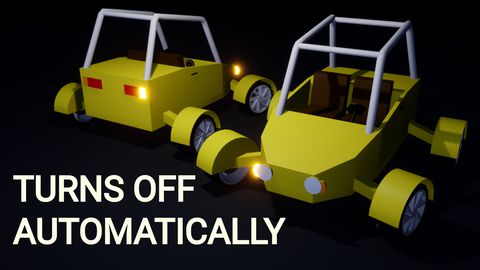
Adding turn signals with automatic turn off | [Part 11] Low poly vehicle for UE4
Tutorials Unreal Engine