How to make a basic physics-based helicopter in Unreal Engine 5
by Arthur Ontuzhan
Posted 3 years, 11 months ago Last edit 3 years, 11 months ago
Categories: Tutorials Unreal Engine Tags: Physics Helicopter UE5
Introduction
In this tutorial, I'll show how to make a basic helicopter in Unreal Engine 5 by using physics components and blueprints. At the end of the tutorial, we should get a somewhat similar helicopter control system as in the GTA games. This will not be step by step tutorial, If you want to use it, you will need to know the basics for UE5 or know how to use google.
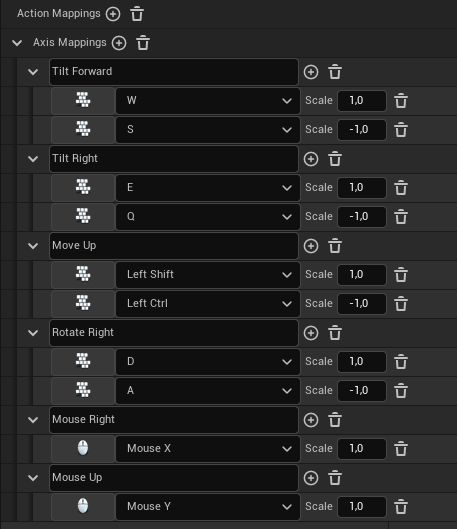
Pawn Setup
Now we can create our helicopter pawn.
- Create a new Pawn Blueprint. You can do it in several ways. If you don't know how to do that, just google "Creating Blueprint Classes Unreal Engine" or something like that. Just make sure to set Pawn as the parent class for your blueprint.
- Add a Static Mesh component to your blueprint and make it the Root Element of blueprint. To make it the root element, just drag it over a Default Scene Root component.
- Under the Static Mesh component add a Physics Thruster component as a child.
- Under the Static Mesh component add a Spring Arm component as a child.
- Under the Spring Arm component add a Camera component as a child.
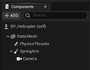
If you did everything right, you should get a similar view in the blueprints components tab as in the image above.
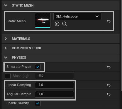
Now we need to change some settings for the Static Mesh component:
- Set its mesh. Use some mesh that has collisions generated for it. I'm using low poly helicopter mesh, that I made using Blender.
- Set it to simulate physics.
- Change Linear Damping and Angular Damping to 1, later you can adjust these values for your own needs.
Changes for Physics Thruster component:
- Move it to the location, from where you want your helicopter's thrust to come. In my case, it's the middle of the helicopter's rotor.
- Rotate it, so its positive X-axis would look straight down. In the image below you can see, that the red arrow should look straight bottom.
- Set it to Auto Activate.
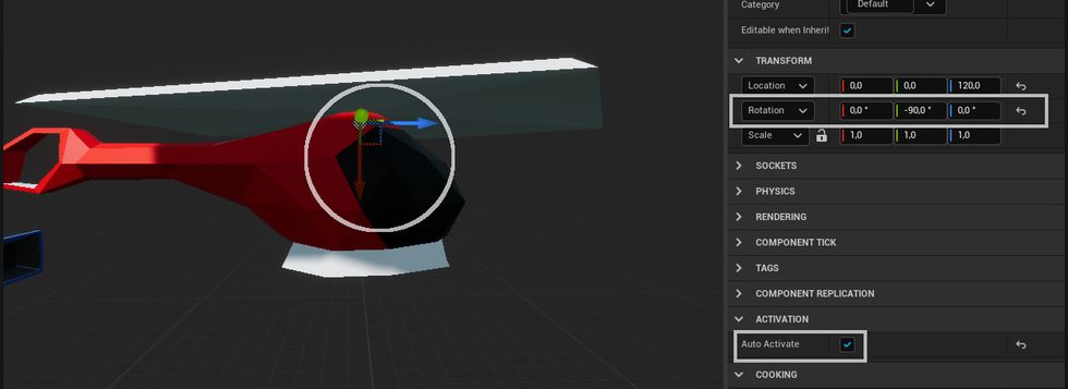
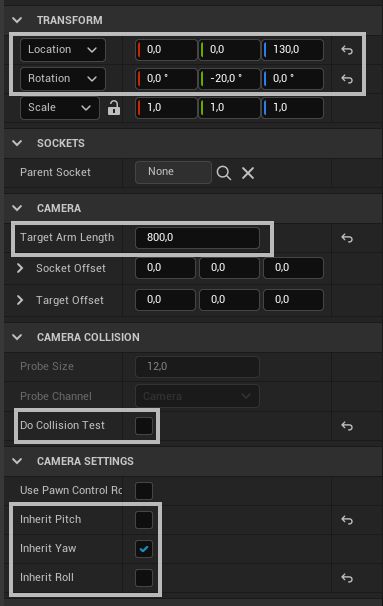
Changes for the Spring Arm component:
- I increased its Target Arm Length to 800.
- Moved it on the top of the mesh, and set its Y(Pitch) rotation to -20.
- Set Do Collision Test to False.
- Unchecked Inherit Pitch and Inherit Roll.
These are just settings I prefer. Just set it as it will feel best for you. These settings will not impact the movement of the helicopter.
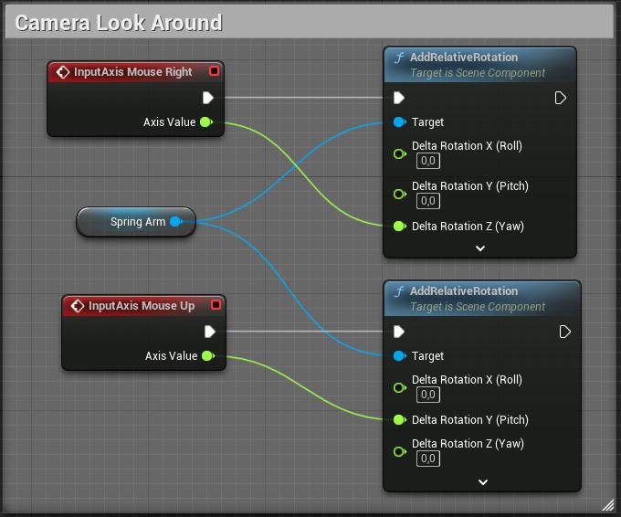
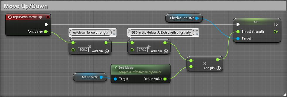
So what do these blueprints do? So by default, Unreal Engine gravity is 980 units strong. In these blueprints, we take input Axis Value and multiply it by 100, and then to that we add 970, and after that, we multiply that value by the mass of our mesh and set that value as strength of the Physics Thruster. Why do we need to multiply the value with mass? F = m x a (force = mass x acceleration).
If we press the "Move Up" key, we will get 1x100 + 970 = 1070 that's larger than 980, so our helicopter will raise. If we press down, -1x100 + 970 = 870 that's smaller than 980, so our helicopter will slowly move down. If we don't press any key, the value will be 970, that's 10 units less than 980, so our helicopter will very slowly move down.
This issue happens because our thruster is not located above the center of mass of our static mesh. If you didn't have any issues, then you just got lucky by having your thruster placed above the center of mass of your model. To fix this issue, we either move thruster over the center of mass or just add offset to the static mesh center of mass. The second solution seems better for me.
- In the blueprint's Event Graph make blueprints that you see in the image below.
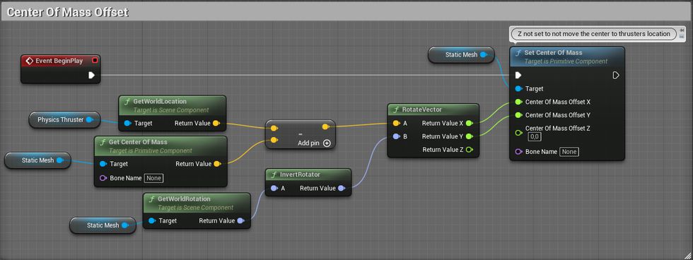
In these blueprints, we take a difference from Physics Thruster's world location and Center Of Mass world location and then rotate it by inverted Mesh World Rotation. We need to rotate difference by world rotation because we are setting offset of the center of mass that's using the local position of mesh. Also, we aren't using a difference's Z value so we wouldn't offset the center of mass right in the physics thruster's location.
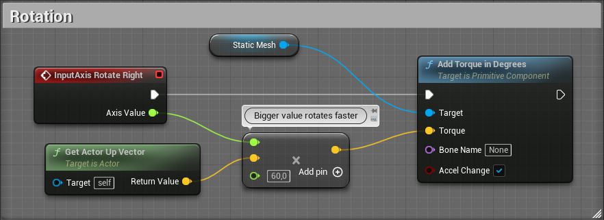
In these blueprints, we are just adding torque around the Up Vector of the mesh. By checking Accel Change on Add Torque in Degrees node, we don't need to count in the mass of the mesh.
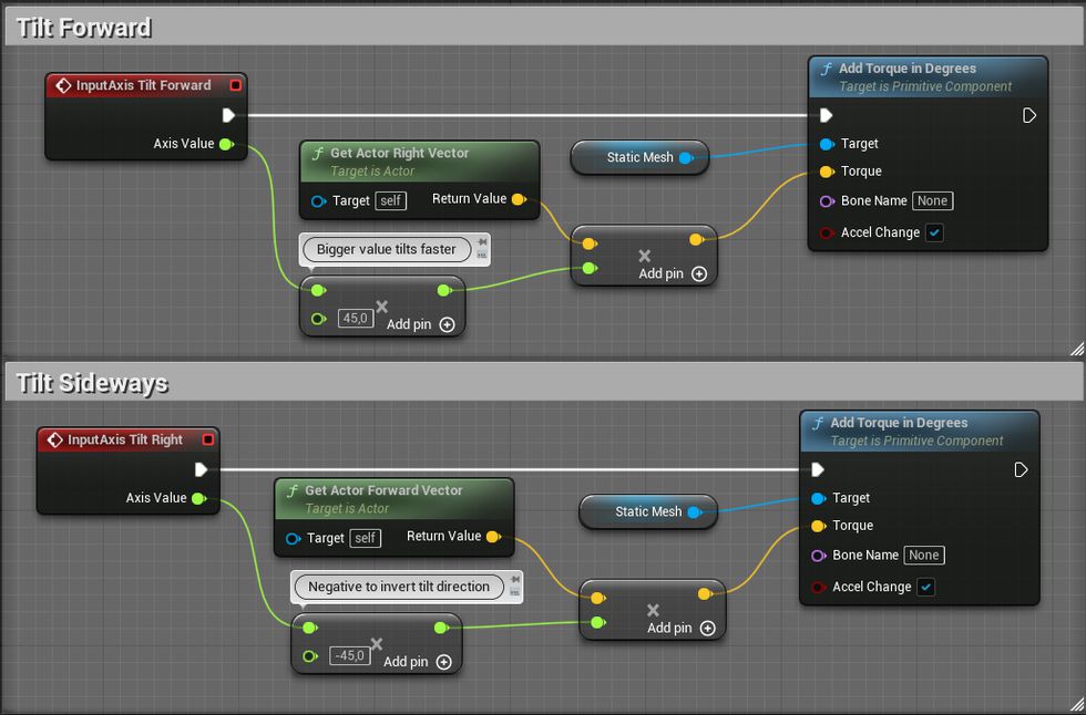
In these blueprints, we are basically doing the same thing as we did in the previous blueprint, but instead of using the Up Vector, we use the actor's Right and Forward vector for the ability to rotate around the other 2 axes.
Limiting pitch and roll
Now, we should be able to move up, down, and tilt to all sides with our helicopter, but I wanted to control feel more like GTA helicopter controls, where you press forward, and you move forward, not endlessly tilt forwards until the helicopter turns over and falls down. Also, if we release tilting input, it will not try to tilt the helicopter back to its "normal" position.
So if we want our controls to feel more like GTA like helicopter, then we need to make some limits for its tilting and make it return to its "normal" position when we don't want it to tilt.
- In the blueprint's Event Graph adjust tilting blueprints that you see in the image below.
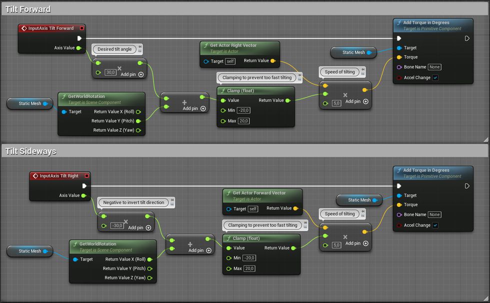
So what do these blueprints do? We take the input axis value, and then multiply it by our desired tilt angle. Then, to that value, we add world rotation from a specific axis and clamp that in the -20 to 20 range. Then we multiply that value by either the Right or the Forward vector and multiply it by an additional value, which increases the speed of rotation.
For example, if we push the "Move Forward" key, we will get a 1 x 30 value for our desired angle. If our helicopter has a pitch 0, then we will get a 0 + 30 value, which will get clamped to 20 after it goes through the clamp node. Then we will tell, that we want to add 5 x 20 torque to our static mesh around the Right Vector axis. If we keep holding our "Move Forward" key, it means that in each frame our pitch value moves closer to the -30 value, because of applied torque. Because pitch value will get closer to -30, our sum with the axis desired rotation value will get smaller. Because the sum is getting smaller, it means, that also applied torque will get smaller. Eventually, that sum will get close to 0 and a barely noticeable amount of torque will get applied, and helicopter pitch will hover around our desired rotation. It might go past the value if we apply too much torque, but when it goes past the value, the sum will become negative, and we will start to apply torque to the opposite direction to get the pitch back to our desired rotation. We are using a clamp node, so we wouldn't get a too strong torque added to the helicopter. For example, when our helicopter pitch is -30 and we suddenly want it to change to 30, we will get a sum that's 60 units big, multiply that by an additional 5 for our speed multiplier, and we will get 300 units of force, instead of our desired 100.
Fixing altitude loss issue
Now tilting works in a similar way as in GTA games, but there's still one really noticeable problem. When we tilt helicopter we see that it starts to move towards the side we tilt, but also we start to quickly lose altitude. At the start, we set our thruster strength just strong enough to move our helicopter up, but we didn't count in that it will also need to move the helicopter other ways. So we need to adjust thruster strength accordingly to helicopters rotation.
- In the blueprint's Event Graph adjust move up/down blueprints that you see in the image below.

All we did for this blueprint is, we are dividing our desired strength value with the Z value of our actor's Up Vector. If you will tilt your helicopter over 90 degrees, this solution will require some more additions to get it working without huge issues.
So the problem, in this case, was that when we rotate our helicopter, the thruster's force isn't fully applied to Z-axis anymore, it starts to apply force on other axes since the length of the force vector stays the same. We need to find a way, how to adjust the thruster's strength, so the Z value of the force vector would stay the same.
At first, I was thinking, I'll probably need to use the Pythagoras theorem to get the desired strength value because I can clearly see a right triangle in this situation. I would take an angle of helicopters rotation, then by knowing the length of the thrusters force vector, I would calculate how much force is going straight down Z-axis and then I would simply divide that value by the strength of the thruster to see what's the ratio between two, and then get a new strength value for thruster by simply dividing current strength with the ratio value.
But then I figured out a simpler solution. So there is an actor's Up Vector, that's 1 unit long, and is pointing in the opposite direction of our thrusters force vector. So it's like 1 unit long force vector of our thruster, but it's pointing in opposite direction. So in the solution I mentioned before, I needed the Pythagoras theorem, to find how much force is applied on Z-axis, if I get Up Vector, I just can look Z value of it, I don't need to use the Pythagoras theorem for that. And if I want to find the ratio between the Z value and the length of the vector, I don't really need to do any math. A unit vector is one unit long, dividing things by 1 you get the same value, so the Z value of the vector is the ratio by how much I would need to divide Up Vector to get its Z value to 1. We can use the same ratio value for our thruster, because it's basically mirrored vector, but with different lengths. So if we divide thruster strength with the Up Vector Z value, we will get constant downforce from our thruster.
Share on
